
F 350 2WD Pickup V8-460 7.5L VIN G EFI (1997)
9. Coat the threads of the attaching bolts with Pipe Sealant with Teflon(R) D8AZ-19554-A or equivalent oil resistant sealer meeting Ford
specification WSK-M2G350-A2 and install the screws.
10. While pushing in on Front Cover Aligner T68P-6019-A, tighten the oil pan-to-engine front cover attaching bolts to 8-12 Nm (71-106 inch lbs.).
Remove alignment tool. Tighten the engine front cover-to-cylinder block attaching screws to 16-24 Nm (12-18 ft. lbs.).
11. Apply Ford Multi-Purpose Grease DOAZ-19584-AA or equivalent meeting Ford specification ESB-M1C93-B to front of crankshaft for crankshaft
vibration damper installation.
12. Install crankshaft damper hub on the inner Woodruff key.
13. Apply Gasket Maker E2AZ-19562-B or equivalent meeting Ford specification WSK-M2G348-A5 to the front of the key on the crankshaft, and in
the keyway inside the crankshaft damper spacer, after installing spacer.
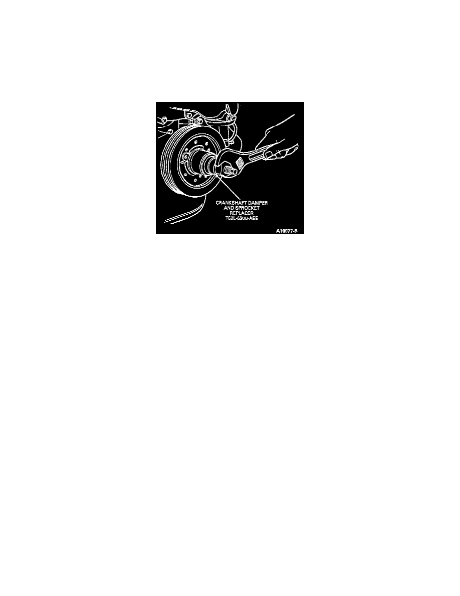
14. Position crankshaft damper Woodruff key and install crankshaft vibration damper using Crankshaft Damper and Sprocket Replacer
T52L-6306-AEE. Install crankshaft vibration damper attaching bolt and washer. Tighten to 95-122 Nm (70-90 ft. lbs.).
15. Install crankshaft pulley to crankshaft vibration damper. Tighten four bolts to 54-71 Nm (40-53 ft. lbs.).
16. Install A/C compressor mounting bracket to cylinder head using four bolts. Tighten to 54-71 Nm (40-53 ft. lbs.). Tighten nut to water pump stud
to 41-54 Nm (30-40 ft. lbs.).
17. Attach A/C compressor to A/C compressor mounting bracket with four bolts and tighten to 24-31 Nm (18-23 ft. lbs.).
18. Attach power steering pump lines to power steering pump. Press power steering pump pulley onto power steering pump. Make sure front surface
of pulley hub is flush with end of pump shaft.
19. Attach generator mounting bracket to cylinder head, cylinder block and water pump with four bolts. Tighten 3/8-inch bolts to 41-54 Nm (30-40 ft.
lbs.) and 7/16 inch bolts to 54-71 Nm (40-53 ft. lbs.).
20. Install secondary air injection pump to generator mounting bracket with two bolts. Tighten to 41-54 Nm (30-40 ft. lbs.). Install secondary air
injection pump pulley. Tighten screws to 12-15 Nm (9-11 ft. lbs.)
21. Install generator adjusting arm to generator mounting bracket and water pump with two bolts. Tighten to 41-54 Nm (30-40 ft. lbs.).
22. Install generator to generator mounting bracket using two bolts. Do not tighten bolts until drive belt has been tensioned. Install drive belts and
adjust drive belt tension to specifications.
24. Position radiator to lower support. Position upper radiator support bracket to radiator, and install attaching bolts. Connect upper radiator hose and
lower radiator hose at engine. Connect transmission oil cooler lines.
25. Place fan blade inside fan shroud and set in position in vehicle. Position the fan blade and fan clutch on the water pump pulley. Install and tighten
the attaching bolts to 16-24 Nm (12-18 ft. lbs.). Install screws attaching fan shroud to radiator.
26. The crankcase oil should be drained and refilled with the proper grade and quantity of engine oil before starting the engine.
27. Install heater return hose to water pump. Fill and bleed the cooling system.
28. Connect battery ground cable.
NOTE: When the battery has been disconnected and reconnected some abnormal drive symptoms may occur while the powertrain control module
(PCM) relearns its adaptive strategy. The vehicle may need to be driven 16 km (10 miles) or more to relearn the strategy.
29. Run engine at fast idle and check for coolant and oil leaks. Adjust ignition timing to specification listed on the vehicle emission control
information (VECI) decal.