
F 350 2WD Pickup V8-7.3L DSL (1988)
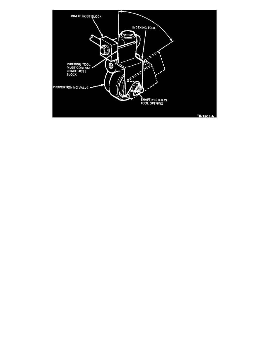
Figure 9
5.
Rotate the valve shaft one (1) full turn in either direction. Position the shaft with the flat at the bottom and parallel with the ground, Figure 8.
6.
Install the indexing tool, (T90T-2588-A) on the shaft so the flat on the tool aligns with the flat on the valve shaft. Make sure the valve shaft is
nested fully in the tool opening and that the upper surface of the tool rests on the valve body, Figures 8 and 9.
7.
Make sure the tool and valve shaft are firmly engaged. Rotate the indexing tool counter-clockwise until the edge surface of the tool contacts the
brake hose block, Figure 9.
8.
While holding the indexing tool in the position established in Step 6, install the leading arm of the linkage assembly over the splined section of the
valve shaft. Use a 1/2" deep socket as a driver and tap it with a hammer to fully seat the linkage on the splines.
9.
Re-install the valve shaft nut removed in Step 1. Tighten the nut to a torque of 8-10 lb.ft. (11-14 N-m).
10.
Remove the indexing tool and save for future use.
NOTE:
THE INDEXING TOOL IS FOR USE ON F-SUPER DUTY TRUCKS ONLY.
PART NUMBER
PART NAME
CLASS
E8TZ-2C 193-A
Linkage Assembly
C
E8TZ-2B547-B
Height Sensing Valve
C
E9TZ-2W125-A
Valve Shaft Positioner
C
E8TZ-2L193-A
Linkage - Kit
C
Warranty and Labor Information
OTHER APPLICABLE ARTICLES: 88-13-8
WARRANTY STATUS: Eligible Under Basic Warranty Coverage
OPERATION
DESCRIPTION
TIME
892515A
Perform Procedure A
0.6 Hr.
892515B
Perform Procedure B
1.0 Hr.
892515C
Perform Procedure C
0.6 Hr.
DEALER CODING
BASIC PART NO. CONDITION CODE
2B547
53
OASIS CODES:
3050, 3051