
F 350 2WD Pickup V8-7.3L DSL (1988)
rotated.
Removal
1. Disconnect the battery ground cable.
2. Remove the steering wheel and pad assembly. Refer to Steering Wheel: Service and Repair.
3. Remove the turn signal lever from the steering column.
4. To gain access to the ignition switch remove the steering column trim shrouds from the steering column. Detach and lower the steering column
assembly from the brake pedal support bracket. Refer to Steering Column: Service and Repair: Removal/Installation.
5. Remove the ignition switch and key warning buzzer terminal and pin it in the LOCK position. Refer to Ignition Switch: Adjustments.
6. Remove the turn signal switch from the column assembly. Refer to Steering Column: Service and Repair: Removal/Installation.
Removing Flange Casting
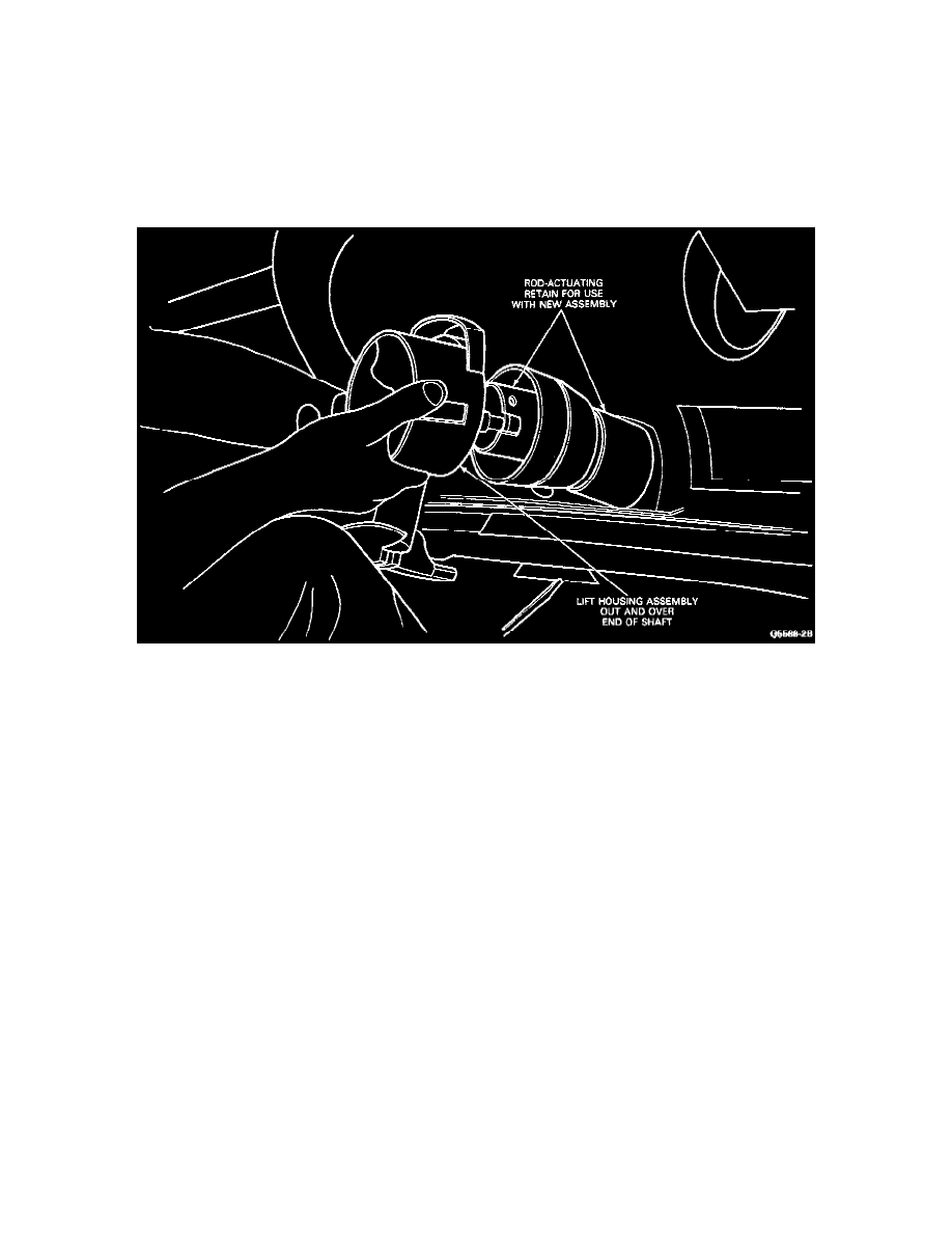
7. Remove the upper bearing snap ring and the (2) T-bolt retaining nuts that secure the flange casting to the outer tube. Remove the entire flange
casting assembly, the upper shaft bearing, the lock cylinder assembly, the ignition switch actuator and the ignition switch actuator rod by pulling
the assembly over the end of the steering column shaft.
8. Remove the lock actuator insert, the T-bolts, and the PRND2 1 insert on automatic transmissions or the key release lever assembly on manual
transmissions.
9. Replace the above assembly with a new assembly consisting of:
(1) Flange.
(1) Lock Cylinder Assembly.
(1) Lock Gear, Steering Column Lock.
(1) Bearing, Steering Column Lock.
(1) Retainer, Steering Column Upper Bearing.
(1) Actuator Assembly, Steering Column Lock.
10. Install the key release lever assembly on 4-speed equipped vehicles and the PRND21 insert on vehicles with automatic transmission. Install the
T-bolts and lock actuator insert.
NOTE: Retain the ignition switch actuating rod from the removed casting assembly and use it with the new flange casting assembly.
Installation
1. Reassemble the above parts, install a new upper shaft bearing and set the actuator to the drive gear.
2. Install the turn signal-hazard warning switch and key warning buzzer. Refer to Steering Column: Service and Repair: Removal/Installation.
3. Install the ignition switch, check and/or adjust for proper function. Refer to Ignition Switch: Adjustments.
4. Install the steering column assembly to the brake pedal support bracket. Refer to Steering Column: Service and Repair: Removal/Installation.
5. Install the steering column trim shrouds, steering wheel and pad assembly. Refer to Steering Column: Service and Repair:
Removal/Installation.
6. Install the turn signal lever.
7. Using the ignition key, ROTATE the lock cylinder to insure correct mechanical operation in all positions.
8. Connect the battery ground cable.
9. Check for proper start in Park and Neutral. Also check to make certain that the start circuit CANNOT be actuated in the DRIVE and REVERSE