
F 350 2WD Super Duty V10-6.8L (2009)
a. Refer to the appropriate vehicle line and microphone illustration(s) below for microphone installation and wire splicing locations. Refer to
Wiring Diagram (WD), Section 5-1 for recommended splicing methods.
b. Ensure the SYNC microphone wires are secure and do not interfere with vehicle operation or functionality.
c. The microphone is directional. Make sure the microphone is always positioned so wire length is minimized from view. When installing the
microphone adjacent to trim, place microphone as close to trim as possible to help minimize visible wire.
2008-2009 Edge / MKX
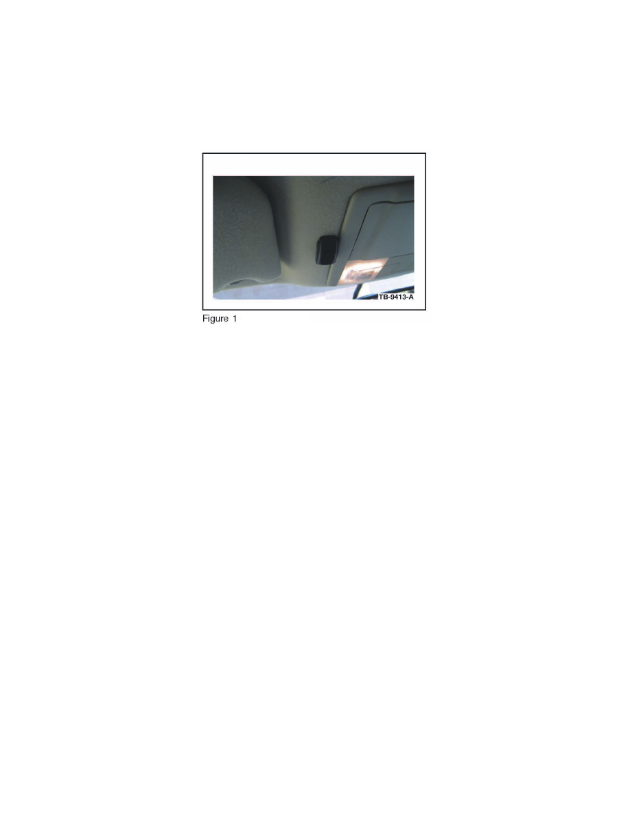
1. Remove the protective backing from the adhesive on the microphone and attach the microphone. (Figure 1)
^ Firmly press the microphone into place.
^ Ensure the microphone is parallel and adjacent to overhead console trim.
2. Lower the overhead console. Refer to WSM, Section 417-02 for additional information.
3. Route microphone cable up through existing hole in the headliner, and over to the driver side A-pillar. It may be necessary to slightly drop headliner
to run microphone cable. Refer to WSM, Section 501-05 for additional information.
4. Install overhead console; ensure microphone cable enters the overhead console trim directly behind microphone as shown.
5. Gain access to connectors 210 and 211 in the left A-pillar. Refer to online WD, Section 124-1 for links to location and connector views.
6. Identify circuits VMM13 (YE-GN), RMM13 (BU), and DMM13 (shield) from C211. Cut the three circuits on the female side of the connector
(14334 harness).
7. Identify circuits CBP41 (BU) and GD133 (BK) from C210.
8. Splice the five jumper harness wires into the following circuits:
^
Blue jumper harness wire to CBP41 (BU) and any black jumper harness wire to GD133 (BK).
^
Ensure original circuits remain connected in splice.
^
Yellow jumper harness wire to VMM13 (YE-GN) and remaining black jumper harness wires to RMM13 (BU) and DMM13 (shield).
^
Only splice into the cut wires heading in the direction of the connector. Tape off and secure the cut wire ends heading up the A-pillar as they are
no longer used.
9. Attach the microphone connector to the jumper harness connector.
10. Bundle and tuck the remainder of the microphone cable over the front of the headliner.
2009 Escape / Mariner