
F 350 2WD Super Duty V10-6.8L (2009)
-
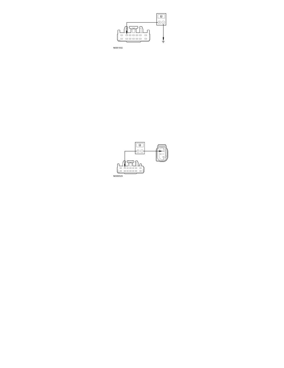
Is the resistance greater than 10,000 ohms?
Yes
GO to C5.
No
REPAIR circuit LCA16 (GN). CLEAR the DTCs. REPEAT the self-test.
-------------------------------------------------
C5 CHECK THE BRAKE PRESSURE TRANSDUCER SUPPLY CIRCUIT FOR AN OPEN
-
Measure the resistance between TBC module C2142-6, circuit LCA16 (GN), harness side and brake pressure transducer C147-3, circuit LCA16
(GN), harness side.
-
Is the resistances less than 5 ohms?
Yes
GO to C6.
No
REPAIR circuit LCA16 (GN). CLEAR the DTCs. REPEAT the self-test.
-------------------------------------------------
C6 CHECK THE BRAKE PRESSURE TRANSDUCER FOR A SHORT
-
Measure the resistance between brake pressure transducer C147, pin-1, component side and brake pressure transducer C147, pin-3, component
side while firmly pressing and releasing the brake pedal.
-
Is the resistance less than 5 ohms?
Yes
INSTALL a new brake pressure transducer. Make sure to LUBRICATE the O-ring seal with clean, specified brake fluid before installation. CLEAR the
DTCs. REPEAT the self-test.
No
CONNECT C147 and C2142, ATTEMPT to recreate the DTC by flexing the wire harness at the brake pressure transducer. If the DTC returns,
REPAIR circuit LCA16 (GN). CLEAR the DTCs. REPEAT the self-test. If the DTC does not return, CHECK the brake pressure transducer connector
for corrosion, pushed-out pins and spread terminals. REPAIR the brake pressure transducer connector as necessary. CLEAR the DTCs. REPEAT the
self-test.
If the connectors are OK, GO to C7.
-------------------------------------------------
C7 CHECK FOR CORRECT TBC MODULE OPERATION