
F 350 2WD Super Duty V10-6.8L (2009)
If any of the circuits are shorted past the third level (if DTCs have been retrieved 3 successive times with the short circuit not having been repaired), then
DTCs B106F and B1342 are set along with the associated continuous DTC. These DTCs (B106F and B1342) cannot be cleared and the module must be
replaced.
The initial short circuit must be successfully repaired and its associated DTC cleared before the SJB is replaced or the new SJB may experience one or
more of the short circuit tolerance levels being used up, possibly unnecessarily causing a repeat replacement of the module.
DTC B106E sets when the SJB has disabled a circuit due to a repetitive fault causing a circuit overload. A corresponding DTC for the circuit in question
will also be set.
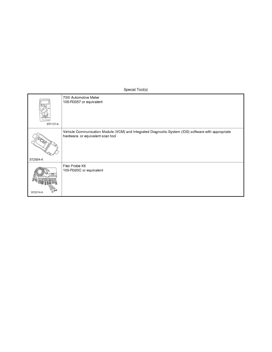
Special Tools Used With Diagnostics
Smart Junction Box (SJB)
Principles of Operation
Upfitter Relay Box
Principles of Operation
NOTE: The Smart Junction Box (SJB) is also known as the Generic Electronic Module (GEM).
When the vehicle's ignition key is in the ON position, the upfitter switch assembly receives voltage through the SJB fuse 42 (10A) which is distributed to
the 4 circuit control switches. When a control switch is closed it supplies voltage to 1 of the 4 upfitter relays (solenoid side) in the upfitter relay box,
closing that relay. Voltage is supplied to the switched side of the upfitter relay circuits from the Battery Junction Box (BJB) for relays No. 1 and No. 2;
and from the SJB for relays No. 3 and No. 4. When the relay closes, voltage is supplied through the relay to the output circuits (and to the blunt cut ends)
located under the LH side of the instrument panel. The output circuits (at the blunt cut ends) supply voltage to the installed accessories that have been
connected to the upfitter relay box.
Inspection and Verification
Upfitter Relay Box
Inspection and Verification
1. Verify the customer concern.
2. Visually inspect for obvious signs of electrical damage.
Visual Inspection Chart