
F 350 2WD Super Duty V10-6.8L (2009)
-
Are all the upfitter accessories inoperative?
Yes
VERIFY the SJB fuse 42 (10A) is OK. If OK, GO to K4. If not OK, REFER to the Wiring Diagrams to identify the possible causes of the circuit short.
No
GO to K2.
-------------------------------------------------
K2 CHECK THE UPFITTER RELAY GROUND CIRCUITS
-
Ignition OFF.
-
Disconnect: Negative Battery Cable.
-
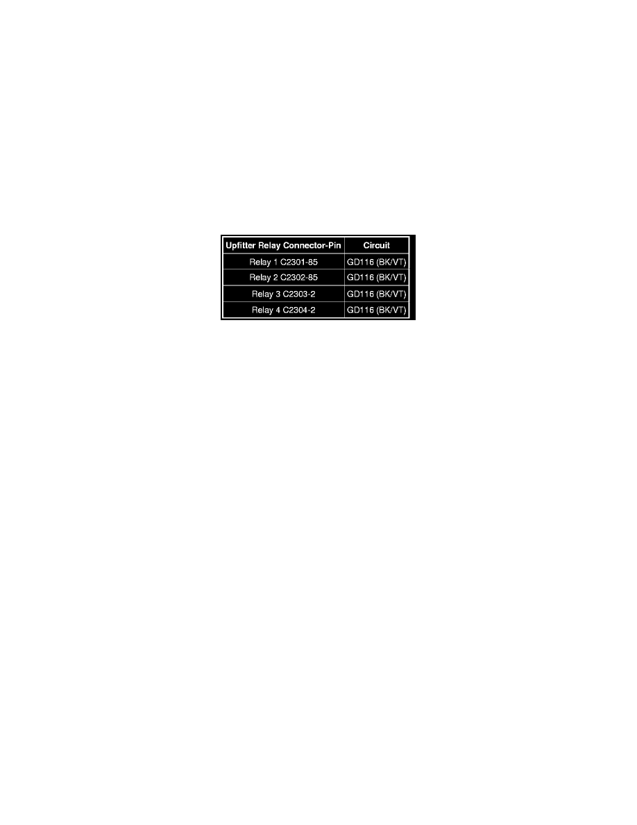
Disconnect: Upfitter Relay 1 C2301, Relay 2 C2302, Relay 3 C2303, Relay 4 C2304.
-
Measure the resistance between the upfitter relay box, harness side and ground as follows:
-
Are the resistances less than 5 ohms?
Yes
CONNECT the negative battery cable. GO to K3.
No
REPAIR the circuit. CONNECT the negative battery cable. TEST the system for normal operation.
-------------------------------------------------
K3 CHECK THE UPFITTER SWITCHES FOR SWITCH VOLTAGE
-
Disconnect: Upfitter Switches C2300.
-
Ignition ON.
-
Measure the voltage between the upfitter switches C2300-8, circuit CBP42 (GN), harness side and ground.
-
Is the voltage greater than 10 volts?
Yes
GO to K4.
No
REPAIR the circuit. TEST the system for normal operation.
-------------------------------------------------
K4 CHECK THE UPFITTER SWITCH OPERATION
-
Connect: Upfitter Switches C2300.
-
Turn all the upfitter switches to the ON position.
-
Measure the voltage between the upfitter relay control circuits, harness side and ground as follows: