
F 350 2WD Super Duty V10-6.8L (2009)
Hydraulic Control Assembly - Antilock Brakes: Service and Repair
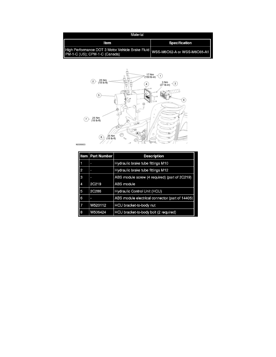
Hydraulic Control Unit (HCU)
Removal and Installation
WARNING: Do not use any fluid other than clean brake fluid meeting manufacturer's specification. Additionally, do not use brake fluid that
has been previously drained. Following these instructions will help prevent system contamination, brake component damage and the risk of
serious personal injury.
WARNING: Carefully read cautionary information on product label. For EMERGENCY MEDICAL INFORMATION seek medical advice.
For additional information, consult the product Material Safety Data Sheet (MSDS) if available. Failure to follow these instructions may result
in serious personal injury.
NOTICE: Do not spill brake fluid on painted surfaces or damage to the surface may occur. If brake fluid is spilled onto a painted or plastic
surface, immediately wash the surface with water.
NOTICE: Electronic modules are sensitive to static electrical charges. If exposed to these charges, damage may result.
NOTICE: When replacing either the Hydraulic Control Unit (HCU) or the Anti-Lock Brake System (ABS) module individually, make sure that
the number of coils (metal cans) in the ABS module equals the number of valves in the HCU. This is an additional method of verifying that the
correct replacement part number has been selected. Failure to follow this instruction may result in damage to the components.
All vehicles
1. Remove the LH front fender splash shield.
Gasoline engine vehicles