
F 350 2WD Super Duty V10-6.8L (2009)
INSTALL a new battery. CLEAR all CMDTCs. TEST the system for normal operation.
-------------------------------------------------
E3 CHECK THE CHARGING SYSTEM VOLTAGE
NOTE: Do not allow the engine rpm to increase above 2,000 rpm while performing this step or the generator may self excite and result in default
charging system output voltage. If engine rpm has gone above 2,000 rpm, shut the vehicle OFF and restart the engine before performing this step.
-
Start the engine.
-
Measure the voltage of the battery:
-
For DTC B1317, turn off all accessories and run the engine at 1,500 rpm for a minimum of 2 minutes.
-
For DTC B1318, turn on headlights and HVAC fan on high and run engine at 1,500 rpm for a minimum of 2 minutes.
-
Is the battery voltage between 13-15.2 volts?
Yes
For DTC B1318, GO to E4.
For DTC B1317, GO to E6.
No
REFER to Charging System to diagnose the charging system. CLEAR all CMDTCs. TEST the system for normal operation.
-------------------------------------------------
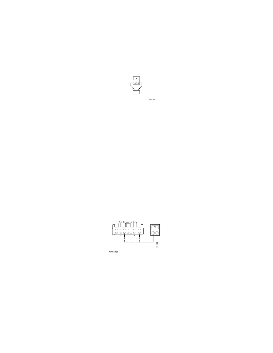
E4 CHECK THE VOLTAGE TO THE TBC MODULE
-
Ignition OFF.
-
Disconnect: TBC Module C2142.
-
Ignition ON.
-
Measure the voltage between ground and:
-
TBC module C2142-8, circuit SBB05 (GY/RD), harness side.
-
TBC module C2142-12, circuit CBP33 (WH/BN), harness side.
-
Are the voltages greater than 10 volts?
Yes
GO to E5.
No
VERIFY BJB fuse 5 (30A) is OK. If OK, REPAIR circuit SBB05 (GY/RD).
VERIFY SJB fuse 33 (10A) is OK. If OK, REPAIR circuit CBP33 (WH/BN).
If either fuse is not OK, REFER to the Wiring Diagrams to identify the possible causes of the circuit short.
CLEAR the DTCs. REPEAT the self-test.