
F 350 2WD Super Duty V10-6.8L (2009)
Yes
GO to A8.
No
GO to A9.
-------------------------------------------------
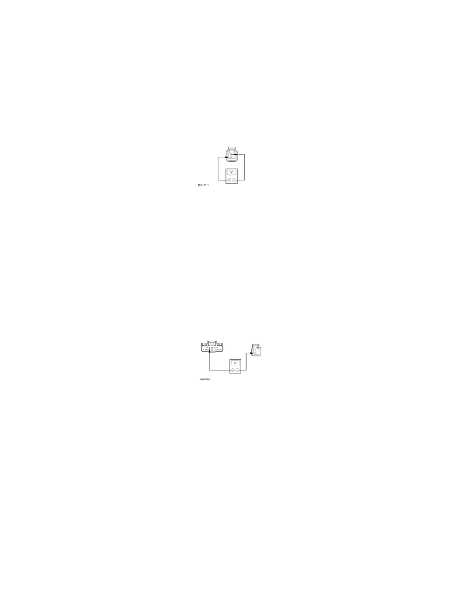
A8 CHECK FOR VOLTAGE TO THE HORN USING THE CONNECTOR GROUND
-
While pressing the horn switch, measure the voltage between the horn C131-2, circuit CRH02 (BU/WH), harness side, and the horn C131-1,
circuit GD124 (BK/VT), harness side.
-
Is the voltage greater than 10 volts?
Yes
INSTALL a new horn. REFER to Horn See: Service and Repair. TEST the system for normal operation.
No
REPAIR circuit GD124 (BK/VT) for an open. TEST the system for normal operation.
-------------------------------------------------
A9 CHECK THE SJB HORN OUTPUT CIRCUIT FOR AN OPEN
-
Disconnect: SJB C2280e.
-
Measure the resistance between the SJB C2280e-5, circuit CRH02 (BU/WH), harness side, and the horn C131-2, circuit CRH02 (BU/WH),
harness side.
-
Is the resistance less than 5 ohms?
Yes
GO to A10.
No
REPAIR the circuit. TEST the system for normal operation.
-------------------------------------------------
A10 CHECK FOR CORRECT SJB OPERATION
-
Disconnect all the SJB connectors.
-
Check for:
-
corrosion
-
damaged pins
-
pushed-out pins
-
Connect all the SJB connectors and make sure they seat correctly.
-
Operate the system and verify the concern is still present.
-
Is the concern still present?