
F 350 2WD Super Duty V10-6.8L (2009)
Any probe entering the terminal may enlarge the contact spring opening creating an intermittent signal.
Insert the correct mating terminal (Location A) from the service kit and feel for a loose fit.
Electrical short inside the harness
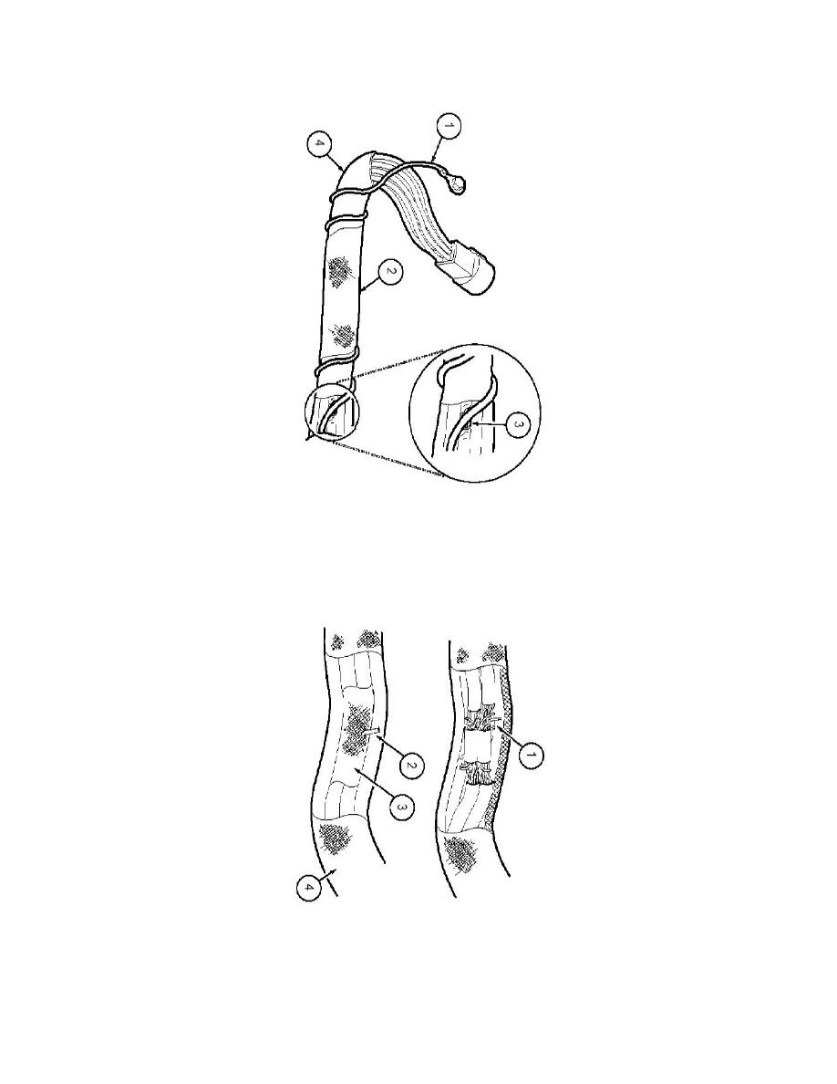
1
= Solder coated wire to ground
2
= Harness protective tape
3
= Intermittent short
Solder coated wire pierced through the insulation of another circuit
4
= Grounding foil
Electrical short within the harness
Splice tape removed
1
= Intermittent short
Splice covered
2
= Wire strand