
F 350 2WD Super Duty V10-6.8L (2009)
2. Visually inspect for obvious signs of electrical damage.
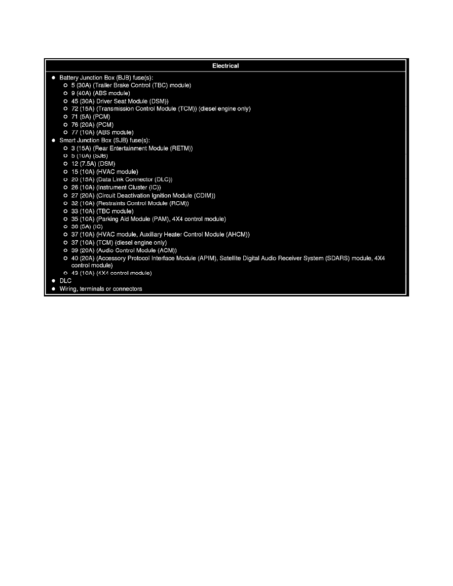
Visual Inspection Chart
Visual Inspection Chart
3. If an obvious cause for an observed or reported concern is found, correct the cause (if possible) before proceeding to the next step.
4. NOTE: Make sure to use the latest scan tool software release.
If the cause is not visually evident, connect the scan tool to the DLC.
5. NOTE: The Vehicle Communication Module (VCM) LED prove-out confirms power and ground from the DLC are provided to the VCM.
If the computer running the Integrated Diagnostic System (IDS) software does not communicate with the VCM:
-
Check the VCM connection to the vehicle.
-
Check the scan tool connection to the VCM.
-
Go To Pinpoint Test W, to diagnose no power to the scan tool. See: Pinpoint Tests/Pinpoint Test W: No Power To The Scan Tool
-
NOTE: The scan tool will first attempt to communicate with the PCM, after establishing communication with the PCM, the scan tool will then
attempt to communicate with all other modules on the vehicle.
If an IDS session cannot be established with the vehicle (IDS may display "No Communication Can Be Established With the PCM"):
-
Choose "NO" when the scan tool prompts whether or not to retry communication.
-
Enter either a PCM part number, tear tag or calibration number to identify the vehicle and start a session.
6. Carry out the network test.
-
If the network test passes, retrieve and record the continuous memory DTCs and proceed to Step 7.
-
If the network test fails, GO to Symptom Chart to diagnose the failed communication network. See: Symptom Related Diagnostic Procedures