
F 350 2WD Super Duty V10-6.8L (2009)
A2 VERIFY THE COMPUTERS AND CONTROL SYSTEMS INFORMATION PINPOINT TEST QA HAS BEEN CARRIED OUT
-
Verify that pinpoint test QA has been carried out.
-
Has pinpoint test QA been carried out?
Yes
GO to A3.
No
REFER to Computers and Control Systems Information, Pinpoint Tests, pinpoint test QA (gasoline engine) or AE (diesel engine) to diagnose no
communication with the PCM.
-------------------------------------------------
A3 CHECK THE HS-CAN TERMINATION RESISTANCE
-
Ignition OFF.
-
Disconnect: Negative Battery Cable.
-
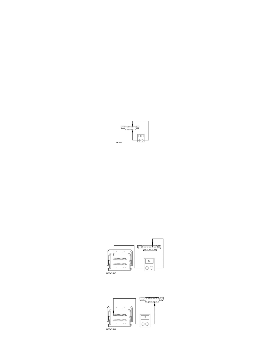
Measure the resistance between the Data Link Connector (DLC) C251-6, circuit VDB04 (WH/BU), harness side and the DLC C251-14, circuit
VDB05 (WH), harness side.
-
Is the resistance between 54 and 66 ohms?
Yes
CONNECT the negative battery cable. GO to A5.
No
GO to A4.
-------------------------------------------------
A4 CHECK THE CAN CIRCUITS BETWEEN THE PCM AND THE DLC FOR AN OPEN
-
Ignition OFF.
-
Disconnect: PCM C175b (Gasoline Engine) or C1232b (Diesel Engine).
-
For gasoline engines, measure the resistance between the PCM C175b-11, circuit VDB04 (WH/BU), harness side and the DLC C251-6, circuit
VDB04 (WH/BU), harness side.
-
For gasoline engines, measure the resistance between the PCM C175b-23, circuit VDB05 (WH), harness side and the DLC C251-14, circuit
VDB05 (WH), harness side.