
F 350 2WD Super Duty V10-6.8L (2009)
CONNECT all modules. CONNECT the negative battery cable. GO to T38.
No
GO to T29.
-------------------------------------------------
T29 VERIFY VEHICLE OPTION CONTENT - AHCM
-
Verify vehicle option content.
-
Is the vehicle equipped with an AHCM?
Yes
GO to T30.
No
REPAIR the circuits. CONNECT all modules. CONNECT the negative battery cable. CLEAR the DTCs. REPEAT the network test with the scan tool.
-------------------------------------------------
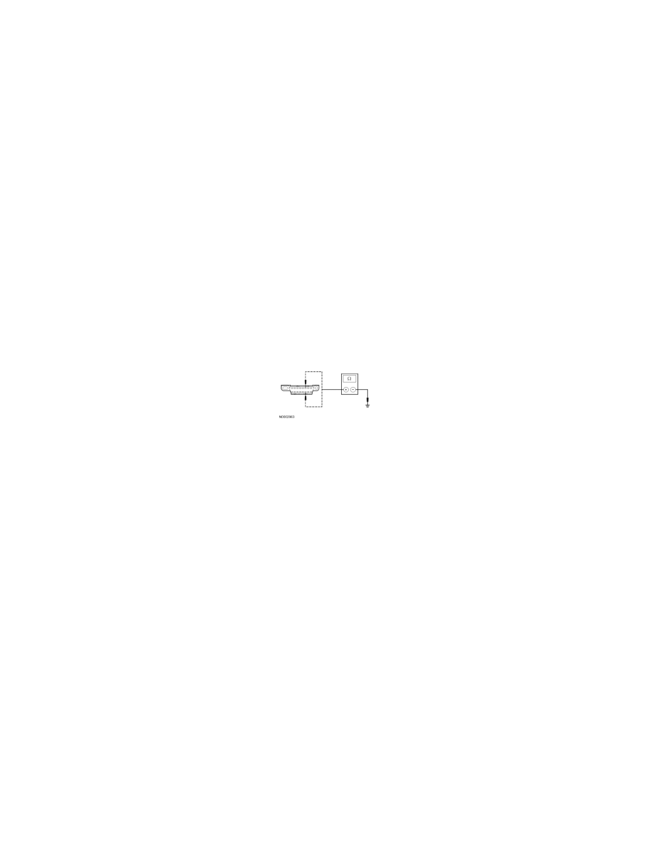
T30 CHECK THE HS-CAN (+) AND HS-CAN (-) CIRCUITS FOR A SHORT TO GROUND WITH THE AHCM DISCONNECTED
-
Disconnect: AHCM C2463c.
-
Measure the resistance between the DLC C251-6, circuit VDB04 (WH/BU), harness side and ground; and between the DLC C251-14, circuit
VDB05 (WH), harness side and ground.
-
Are the resistances greater than 5,000 ohms?
Yes
CONNECT all modules. CONNECT the negative battery cable. GO to T39.
No
REPAIR the circuits. CONNECT all modules. CONNECT the negative battery cable. CLEAR the DTCs. REPEAT the network test with the scan tool.
-------------------------------------------------
T31 CHECK FOR CORRECT PCM OPERATION
-
Disconnect all the PCM connectors.
-
Check for:
-
corrosion
-
damaged pins
-
pushed-out pins
-
Connect all the PCM connectors and make sure they seat correctly.
-
Operate the system and verify the concern is still present.
-
Is the concern still present?
Yes
INSTALL a new PCM. CLEAR the DTCs. REPEAT the network test with the scan tool.
No
The system is operating correctly at this time. The concern may have been caused by a loose or corroded connector. CLEAR the DTCs. REPEAT the
network test with the scan tool.
-------------------------------------------------