
F 350 2WD Super Duty V10-6.8L (2009)
1. Remove the protective backing from the adhesive on the microphone and attach the microphone as shown in the illustration. (Figure 11)
a. Firmly press the microphone into place.
b. Ensure the microphone is parallel and adjacent to overhead console trim.
2. Lower the overhead console. Refer to WSM, Section 417-02 for additional information.
3. Route microphone cable through existing hole in the headliner, and over to the passenger side A-pillar. It may be necessary to slightly drop headliner
to run microphone cable. Refer to WSM, Section 501-05 for additional information.
4. Install overhead console; ensure microphone cable enters the overhead console trim directly behind microphone as shown.
5. Gain access to connector 913 in the right A-pillar. Refer to online WD, Section 124-1 for links to location and connector views.
6. Identify circuits VMM13 (YE-GN), RMM13 (BU), and DMM13 (shield) from C913. Cut the three circuits on the female side of the connector
(14334 harness).
7. Identify circuits CBP02 (GN) and GD139 (BK-YE) from C913.
8. Splice the five jumper harness wires into the following circuits:
^
Blue jumper harness wire to CBP02 (GN) and any black jumper harness wire to GD139 (BK-YE).
^
Ensure original circuits remain connected in splice.
^
Yellow jumper harness wire to VMM13 (YE-GN) and remaining black jumper harness wires to RMM13 (BU) and DMM13 (shield).
^
Only splice into the cut wires heading in the direction of the connector. Tape off and secure the other cut wire ends as they are no longer used.
9. Attach the microphone connector to the jumper harness connector.
10. Bundle and tuck the remainder of the microphone cable above the front of the headliner.
2008-2009 Taurus / Sable / Taurus X
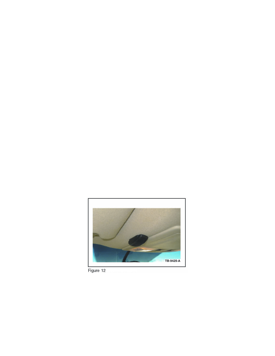
1. Remove the protective backing from the adhesive on the microphone and attach the microphone as shown in the illustration. (Figure 12)
^
Firmly press the microphone into place.
^
Ensure the microphone is parallel and adjacent to overhead console trim.
2. Lower the overhead console. Refer to WSM, Section 417-02 for additional information.
3. Route microphone cable through existing hole in the headliner, and over to the driver side A-pillar. It may be necessary to slightly drop headliner to
run microphone cable. Refer to WSM, Section 501-05 for additional information.
4. Install overhead console; ensure microphone cable enters the overhead console trim directly behind microphone as shown.