
F 350 2WD Super Duty V10-6.8L (2009)
-
Does the PID agree with the brake pedal position?
Yes
GO to B3.
No
GO to B2.
-------------------------------------------------
B2 CHECK THE PCM BOO AND BRAKE PRESSURE APPLIED (BPA) PIDs
NOTE: The BOO PID is derived from the Brake Pedal Position (BPP) (stoplamp) switch and the BPA PID is derived from the speed control
deactivation switch.
-
Enter the following diagnostic mode on the scan tool: DataLogger - PCM.
-
Monitor the BOO and BPA PIDs while pressing and releasing the brake pedal.
-
Do the PIDs agree with the position of the brake pedal ?
Yes
REFER to Information Bus to diagnose the HS-CAN bus.
No
REFER to Cruise Control to diagnose the speed control deactivation switch.
REFER to Brake Lamp to diagnose the stoplamp (BPP) switch. See: Lighting and Horns/Brake Lamp/Testing and Inspection
-------------------------------------------------
B3 CHECK THE BRAKE PRESSURE TRANSDUCER SIGNAL RETURN CIRCUIT FOR A SHORT TO VOLTAGE
-
Ignition OFF.
-
Disconnect: TBC Module C2142.
-
Disconnect: Brake Pressure Transducer C147.
-
Ignition ON.
-
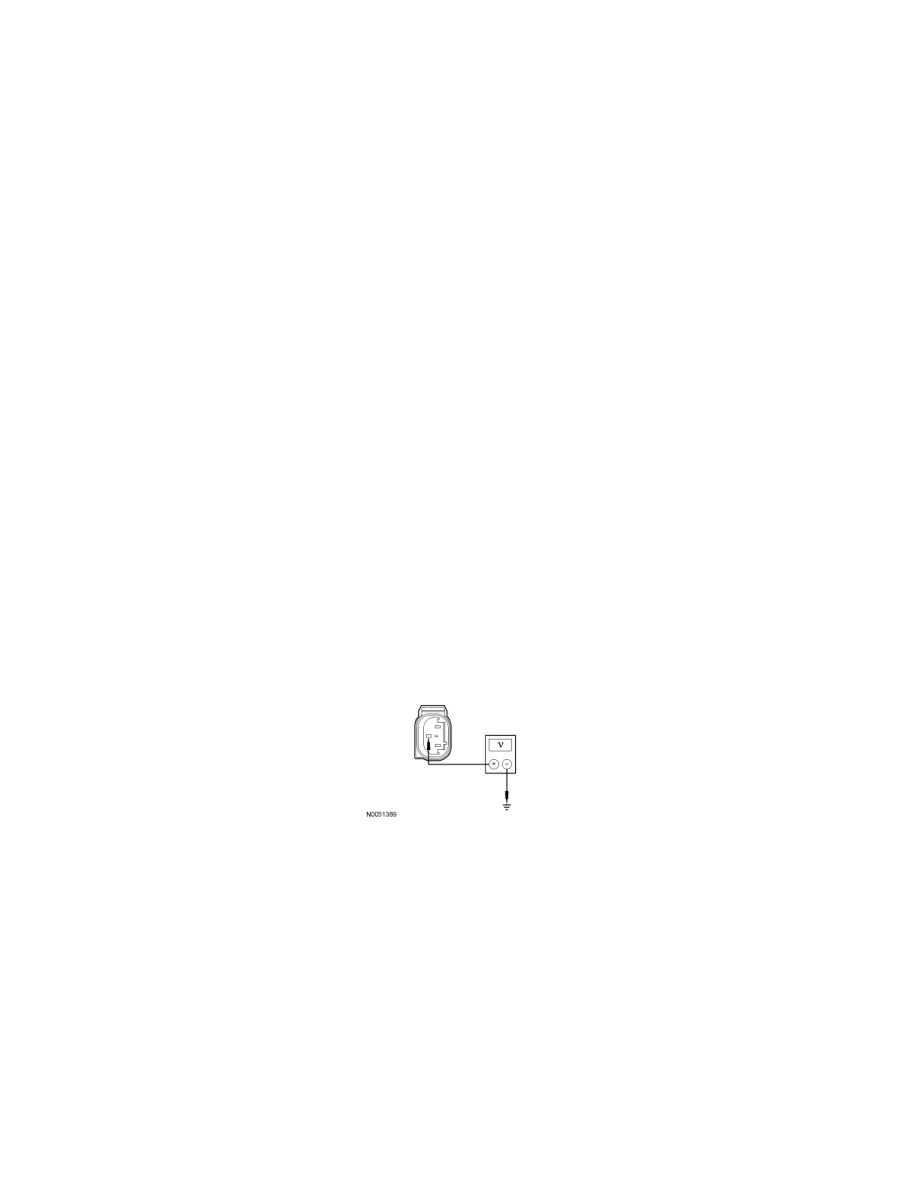
Measure the voltage between brake pressure transducer C147-2, circuit VCA13 (YE/BU), harness side and ground.
-
Is any voltage present?
Yes
REPAIR circuit VCA13 (YE/BU). CLEAR the DTCs. REPEAT the self-test.
No
GO to B4.
-------------------------------------------------
B4 CHECK THE BRAKE PRESSURE TRANSDUCER SIGNAL RETURN CIRCUIT FOR AN OPEN
-
Ignition OFF.
-
Measure the resistance between TBC module C2142-5, circuit VCA13 (YE/BU), harness side and brake pressure transducer C147-2, circuit
VCA13 (YE/BU), harness side.