
F 350 2WD Super Duty V10-6.8L (2009)
REPAIR circuit VCA13 (YE/BU). CLEAR the DTCs. REPEAT the self-test.
-------------------------------------------------
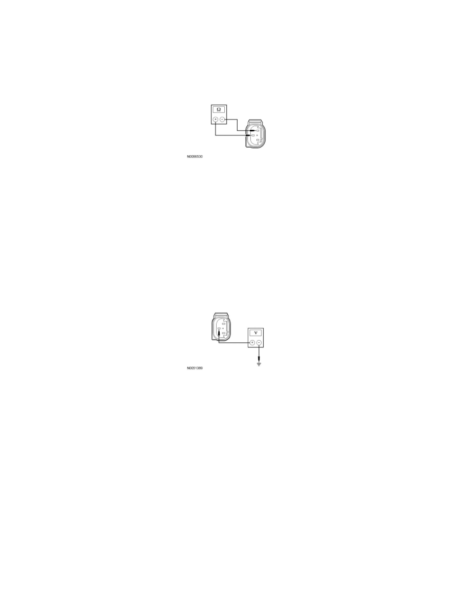
D4 CHECK THE BRAKE PRESSURE TRANSDUCER SENSE CIRCUIT AND SUPPLY CIRCUIT FOR A SHORT TOGETHER
-
Measure the resistance between brake pressure transducer C147-2, circuit VCA13 (YE/BU), harness side and brake pressure transducer C147-3,
circuit LCA16 (GN), harness side.
-
Is the resistance greater than 10,000 ohms?
Yes
GO to D5.
No
REPAIR the affected circuit(s). CLEAR the DTCs. REPEAT the self-test.
-------------------------------------------------
D5 CHECK THE BRAKE PRESSURE TRANSDUCER SENSE CIRCUIT FOR A SHORT TO VOLTAGE
-
Ignition ON.
-
Measure the voltage between brake pressure transducer C147-2, circuit VCA13 (YE/BU), harness side and ground.
-
Is any voltage present?
Yes
REPAIR circuit VCA13 (YE/BU). CLEAR the DTCs. REPEAT the self-test.
No
GO to D11.
-------------------------------------------------
D6 CHECK THE TBC MODULE OPERATION
-
Using the scan tool, clear the TBC module DTCs.
-
Ignition OFF.
-
Disconnect: Brake Pressure Transducer C147.
-
Ignition ON.
-
Enter the following diagnostic mode on the scan tool: Self Test - TBC Module.
-
Retrieve and record the TBC module DTCs.
-
Is DTC C2800 present?
Yes
CHECK the brake pressure transducer connector for corrosion, pushed-out pins and spread terminals. REPAIR the brake pressure transducer connector