
F 350 2WD Super Duty V10-6.8L (2009)
as necessary. If the connector is OK, INSTALL a new brake pressure transducer. Make sure to LUBRICATE the O-ring seal with clean, specified brake
fluid before installation. CLEAR the DTCs. REPEAT the self-test.
No
GO to D7.
-------------------------------------------------
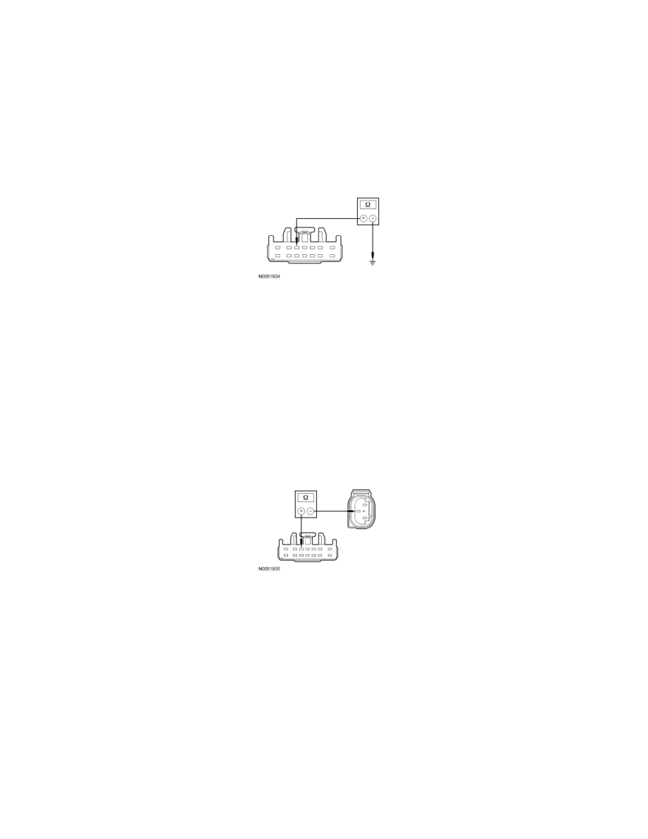
D7 CHECK THE BRAKE PRESSURE TRANSDUCER SENSE CIRCUIT FOR A SHORT TO GROUND
-
Ignition OFF.
-
Disconnect: TBC Module C2142.
-
Measure the resistance between TBC module C2142-5, circuit VCA13 (YE/BU), harness side and ground.
-
Is the resistance greater than 10,000 ohms?
Yes
GO to D8.
No
REPAIR circuit VCA13 (YE/BU). CLEAR the DTCs. REPEAT the self-test.
-------------------------------------------------
D8 CHECK THE BRAKE PRESSURE TRANSDUCER RETURN CIRCUIT FOR AN OPEN
-
Measure the resistance between TBC module C2142-5, circuit VCA13 (YE/BU), harness side and brake pressure transducer C147-2, circuit
VCA13 (YE/BU), harness side.
-
Is the resistance less than 5 ohms?
Yes
GO to D9.
No
REPAIR circuit VCA13 (YE/BU). CLEAR the DTCs. REPEAT the self-test.
-------------------------------------------------
D9 CHECK THE BRAKE PRESSURE TRANSDUCER SENSE CIRCUIT AND RETURN CIRCUIT A SHORT TOGETHER
-
Ignition OFF.
-
Measure the resistance between brake pressure transducer C147-2, circuit VCA13 (YE/BU), harness side and brake pressure transducer C147-1,
circuit RCA16 (BU/BN), harness side.