
F 350 2WD Super Duty V10-6.8L (2009)
Accelerator Pedal Position Sensor: Description and Operation
Engine Control Components
Accelerator Pedal Position (APP) Sensor
The APP sensor is an input to the powertrain control module (PCM) and is used to determine the amount of torque requested by the operator. Depending
on the application either a 2-track or 3-track APP sensor is used.
2-Track APP Sensor
There are two pedal position signals in the sensor. Both signals, APP1 and APP2, have a positive slope (increasing angle, increasing voltage), but are
offset and increase at different rates. The two pedal position signals make sure the PCM receives a correct input even if one signal has a concern. The
PCM determines if a signal is incorrect by calculating where it should be, inferred from the other signals. If a concern is present with one of the circuits
the other input is used. There are two reference voltage circuits, two signal return circuits, and two signal circuits (a total of six circuits and pins)
between the PCM and the APP sensor assembly. The reference voltage circuits and the signal return circuits are shared with the reference voltage circuit
and signal return circuit used by the electronic throttle body (ETB) throttle position (TP) sensor. The pedal position signal is converted to pedal travel
degrees (rotary angle) by the PCM. The software then converts these degrees to counts, which is the input to the torque based strategy. For additional
information, refer to Torque Based Electronic Throttle Control (ETC) See: Powertrain Management/Computers and Control Systems/Electronic Throttle
Control Module/Description and Operation.
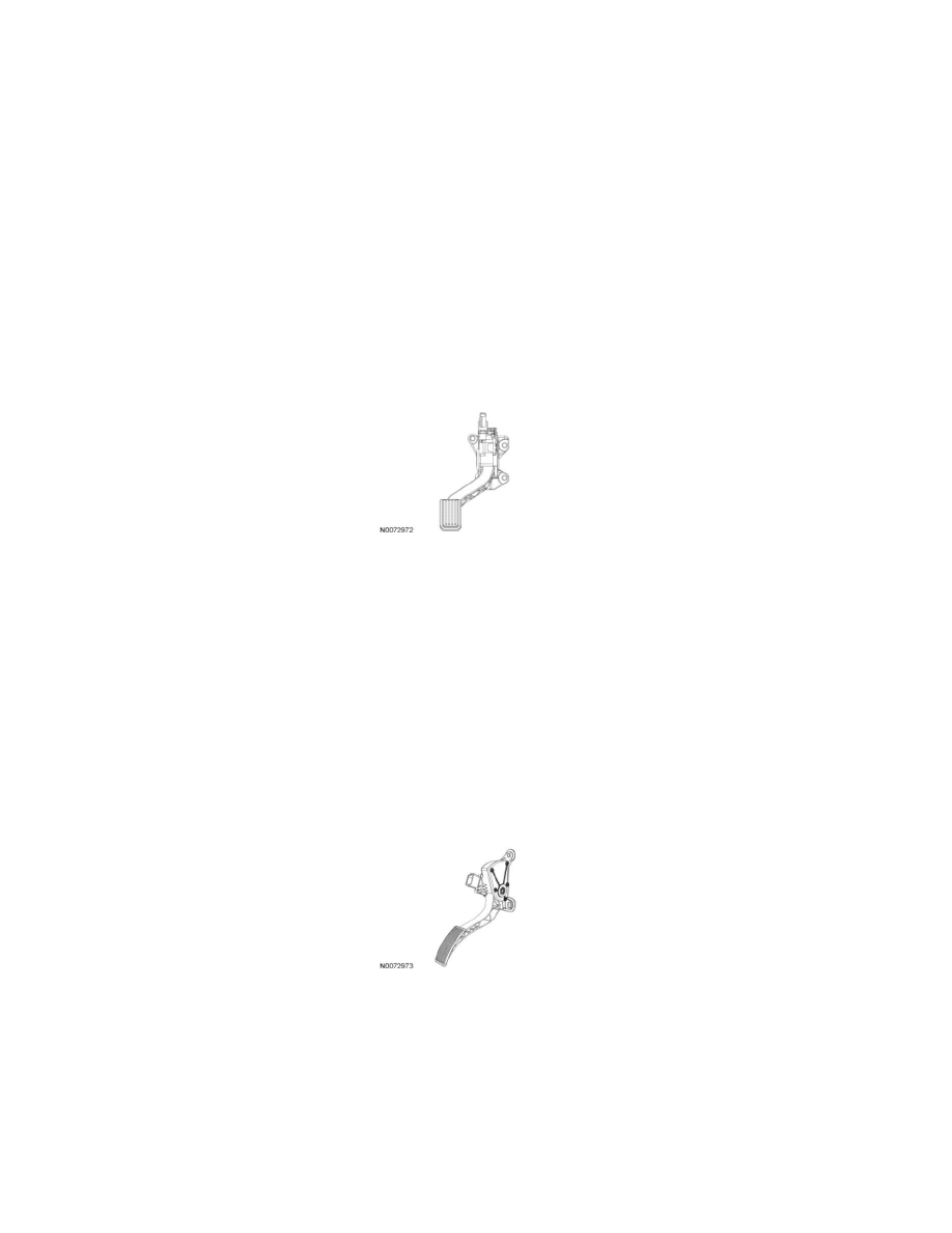
2-Track APP Sensor
Typical 2-Track APP Sensor
3-Track APP Sensor
There are three pedal position signals in the sensor. Signal 1, APP1, has a negative slope (increasing angle, decreasing voltage) and signals 2 and 3,
APP2 and APP3, both have a positive slope (increasing angle, increasing voltage). During normal operation APP1 is used as the indication of pedal
position by the strategy. The three pedal position signals make sure the PCM receives a correct input even if one signal has a concern. The PCM
determines if a signal is incorrect by calculating where it should be, inferred from the other signals. If a concern is present with one of the circuits the
other inputs are used. The pedal position signal is converted to pedal travel degrees (rotary angle) by the PCM. The software then converts these degrees
to counts, which is the input to the torque based strategy. There are two reference voltage circuits, two signal return circuits, and three signal circuits (a
total of seven circuits and pins) between the PCM and the APP sensor assembly. The reference voltage circuits and the signal return circuits are shared
with the reference voltage circuit and signal return circuit used by the electronic throttle body (ETB) throttle position sensor. For additional information,
refer to Torque Based Electronic Throttle Control (ETC) See: Powertrain Management/Computers and Control Systems/Electronic Throttle Control
Module/Description and Operation.
3-Track APP Sensor
Typical 3-Track APP Sensor