
F 350 2WD Super Duty V10-6.8L (2009)
end of the driveshaft.
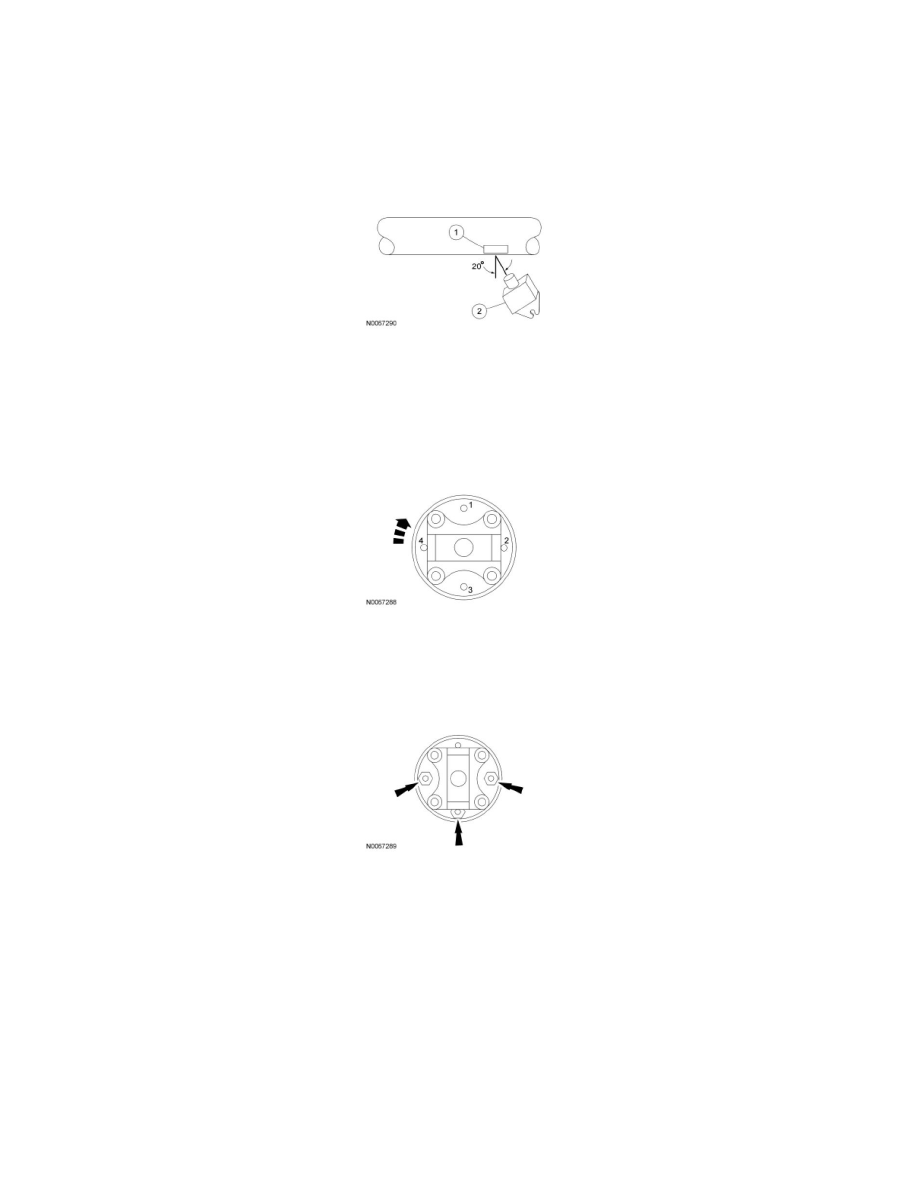
3. Clean an area of the driveshaft and install the reflective tape, then install the photo-tachometer sensor. The sensor should be placed at
approximately a 20-degree angle from perpendicular to the surface of the reflective tape. Make sure the sensor does not get moved during the
balance procedure.
1. Reflective tape.
2. Photo-tachometer sensor.
4. Using the Mastertech(R) Series MTS 4000 Driveline Balance and NVH Analyzer (Vetronix), run a driveshaft balance test with the driveshaft
unmodified.
Vehicles with tapped pinion flanges
5. Label the tapped holes in the pinion flange numerically, starting at the top hole as 1. Mark the remaining holes 2, 3 and 4. Label in the direction of
rotation.
6. Using the Mastertech(R) Series MTS 4000 Driveline Balance and NVH Analyzer (Vetronix), run a second test with the 12 mm (0.47 in) test
weight set screw in the No. 1 hole, previously marked on the pinion flange.
7. Remove the test weight, then install the weight combination directed by the Mastertech(R) Series MTS 4000 Driveline Balance and NVH
Analyzer (Vetronix).
Vehicles without tapped pinion flanges
8. Using the Mastertech(R) Series MTS 4000 Driveline Balance and NVH Analyzer (Vetronix), run a second test with a test weight. Using a metal
band, secure the test weight to the end of the driveshaft. The weight should be placed at the end of the driveshaft tube, as close to the tube-to-yoke
weld seam as possible. Mark the location of the test weight on the driveshaft, as shown in the figure below.
1. Test weight.
2. Tube-to-yoke weld seam.
3. Driveshaft pinion flange.
-
Select the test weight based on driveshaft size. Larger driveshafts use 10 g (0.353 oz). Smaller driveshafts use 5 g (0.176 oz).