
F 350 2WD Super Duty V10-6.8L VIN S (1999)
1.
Raise vehicle on hoist and support front axle.
2.
Remove stability bar, stability bar insulators, and stability bar retainer from axle and links.
3.
Grind off protruding stability bar bracket weldment from the front axle on both spring caps.
NOTE
DO NOT REMOVE ENTIRE WELDMENT, JUST ENOUGH TO ALLOW ATTACHMENT OF STABILITY BAR MOUNTING BRACKET.
THE ISOLATOR MUST CONTACT WELDMENT BASE.
CAUTION
DO NOT GOUGE INTO SPRING CAP OF AXLE.
4.
Drill two (2) 12 mm holes in the axle spring cap weldment on the surface where the stability bar bracket weldment was removed, as follows (RH
side/passenger side described):
a.
Position one (1) hole 40 mm down from the cap's top edge and 25 mm over from cap's outer surface on the outboard side of vehicle.
b.
Position second hole 20 mm down from the cap's top edge and 60 mm over from cap's outer surface on the outboard side of vehicle.
c.
Mounting holes should line up with stability bar mounting bracket so that the bracket opens toward the center of the vehicle and the stability
bar retainer holes are oriented vertically with respect to each other.
5.
Repeat Step 4 in mirror image for LH side/driver side bracket.
6.
Bolt on the Stability Bar Mounting Bracket (F81Z-5486-DB) in orientation described in Step above with two (2) Bolts (N605921-S426) and two
(2) Nuts (N620482-S427) torqued to 47 ±7 N.m (35 ±5 lb-ft) (verify bracket holes are in the vertical position).
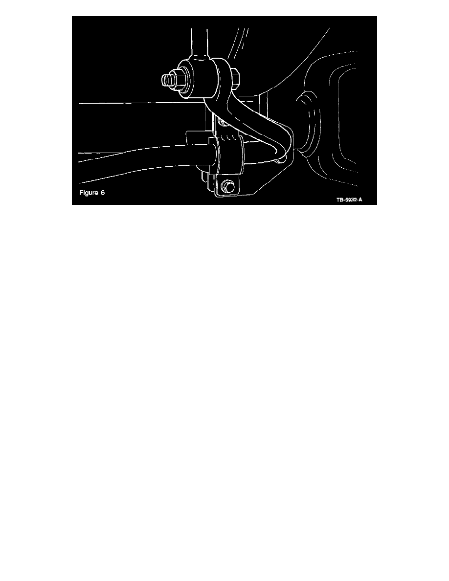
7.
Install Stability Bar (F81Z-5482-FA or -AA) using Stability Bar Retainer (F81Z-5486-AA) with Bolt (N605921-S426) and Nuts (N620482-S427)
torqued to 47 ± 7 N.m (35 ±5 lb-ft).
8.
Attach stability bar to stability bar links with a torque of 80 ± 12 N.m (59 ±9 lb-ft).