
F 350 2WD Super Duty V8-6.4L DSL Turbo (2009)
Fan Clutch: Description and Operation
ENGINE CONTROL COMPONENTS
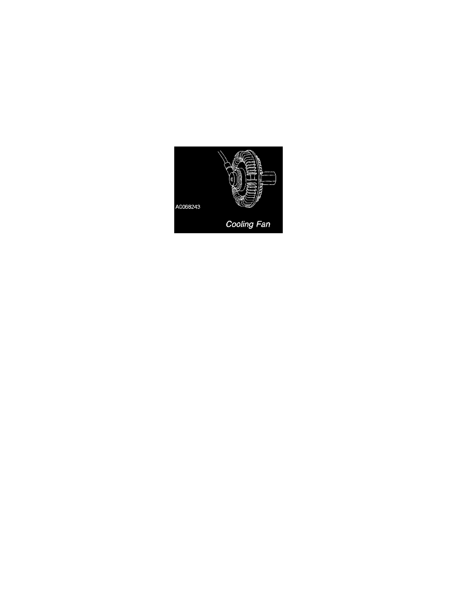
Cooling Fan
The actuator valve controls the fluid flow from the reservoir into the working chamber. Once viscous fluid is in the working chamber, shearing of the
fluid results in fan rotation. The valve is activated by a pulse width modulation (PWM) output signal from the PCM. By opening and closing the fluid
port valve, the PCM controls the fan speed. Fan speed is measured through a Hall effect sensor, and is monitored by the PCM during closed loop
operation. The PCM optimizes the fan speed based on the engine coolant temperature, the engine oil temperature, the fuel rail temperature, the
transmission fluid temperature, the intake air temperature, or air conditioning requirements. When an increased demand for fan speed is requested for
vehicle cooling, the PCM monitors the fan speed through the Hall effect sensor. If a fan speed increase is required, the PCM outputs the PWM signal
to the fluid port, providing the required fan speed increase. During the key on, engine running (KOER) self-test, the PCM commands a 100% duty
cycle. A DTC is set if the PCM detects the voltage on the valve control circuit is not within the expected range or if the fan speed is less than a
calibrated value.
Cooling Fan