
F 350 2WD Super Duty V8-6.4L DSL Turbo (2009)
Engine System - General Information
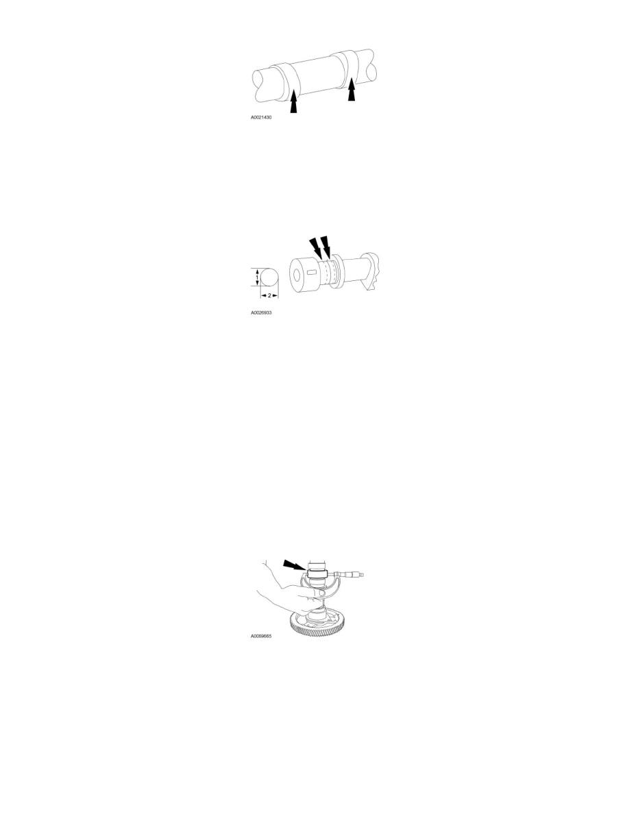
Camshaft Bearing Journal Diameter
NOTE: Refer to the Engine system level for the specification.
1. Measure each camshaft journal diameter in 2 directions.
Engine
Camshaft Bearing Journal Diameter
1. NOTE: This engine utilizes hydraulic valve tappets with roller followers. Therefore, a roller follower guide is needed to maintain correct
roller-to-cam lobe orientation. Normal clearance between the valve tappet and guide allows for slight tracking of the roller across the cam lobe.
This tracking of the valve tappet roller is a normal characteristic as the roller accelerates and decelerates during typical engine operation.
Consequently, a typical wear pattern on the cam lobes will exhibit tracks from side to side and have wide and narrow areas from the loading and
unloading of the follower. The visual wear pattern (tracking) is normal and does not require installation of a new camshaft.
Inspect the camshaft. If any lobes are scuffed, scored or cracked, install a new camshaft.
2. NOTE: When measuring the camshaft with a micrometer, always take 2 measurements 90 degrees apart.
Beyond visual inspection, evaluate camshaft main journal diameter as follows:
-
Use a 50-75 mm (2-3 in) micrometer to measure camshaft bearing journal diameter. Record these measurements for later use in camshaft
bushing inspection. If bearing journals are worn beyond limits, install a new camshaft. For additional information, refer to Specifications.
Engine System - General Information
Camshaft Lobe Lift