
F 350 2WD Super Duty V8-6.4L DSL Turbo (2009)
Normal Operation
The 4X4 control module communicates with the scan tool through the International Standards Organization (ISO) 9141 communications network.
Circuit VDB10 (GY) provides the diagnostic connection to the Data Link Connector (DLC). Voltage for the 4X4 module is provided by circuits CBP35
(YE/GY), CBP43 (GY) and SBP40 (VT/RD). Circuit GD115 (BK/GY) provides ground.
This pinpoint test is intended to diagnose the following:
-
Fuse
-
Wiring, terminals or connectors
-
4X4 control module
PINPOINT TEST P: THE 4X4 CONTROL MODULE DOES NOT RESPOND TO THE SCAN TOOL
NOTICE: Use the correct probe adapter(s) when making measurements. Failure to use the correct probe adapter(s) may damage the
connector.
NOTE: Failure to disconnect the battery when instructed will result in false resistance readings.
-------------------------------------------------
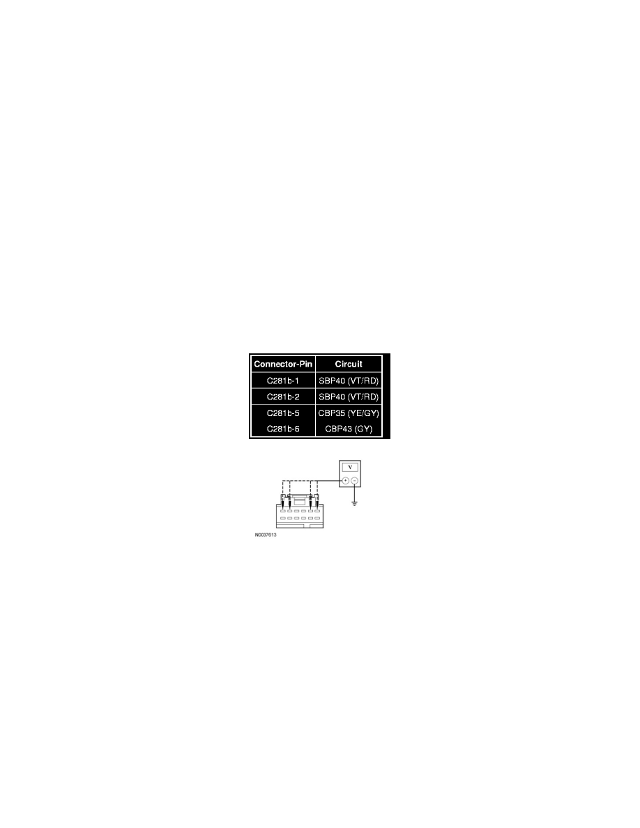
P1 CHECK THE 4X4 CONTROL MODULE VOLTAGE SUPPLY CIRCUITS FOR AN OPEN
-
Ignition OFF.
-
Disconnect: 4X4 Control Module C281b.
-
Ignition ON.
-
Measure the voltage between the 4X4 control module, harness side and ground as follows:
-
Are the voltages at each pin greater than 10 volts?
Yes
GO to P2.
No
VERIFY the Smart Junction Box (SJB) fuses 35 (10A), 40 (20A) and 43 (10A) are OK. If OK, REPAIR the circuit in question. If not OK, REFER to the
Wiring Diagrams to identify the possible causes of the circuit short. CLEAR the DTCs. REPEAT the network test with the scan tool.
-------------------------------------------------
P2 CHECK THE 4X4 CONTROL MODULE GROUND CIRCUIT FOR AN OPEN
-
Ignition OFF.
-
Disconnect: Negative Battery Cable.
-
Measure the resistance between the 4X4 control module C281b-3, GD115 (BK/GY) and ground.