
F 350 2WD Super Duty V8-6.4L DSL Turbo (2009)
No
REPAIR the circuit. CONNECT the negative battery cable. CLEAR the DTCs. REPEAT the network test with the scan tool.
-------------------------------------------------
R6 VERIFY VEHICLE OPTION CONTENT - PAM
-
Verify the vehicle option content.
-
Is the vehicle equipped with a PAM?
Yes
GO to R7.
No
CONNECT the negative battery cable. GO to R9.
-------------------------------------------------
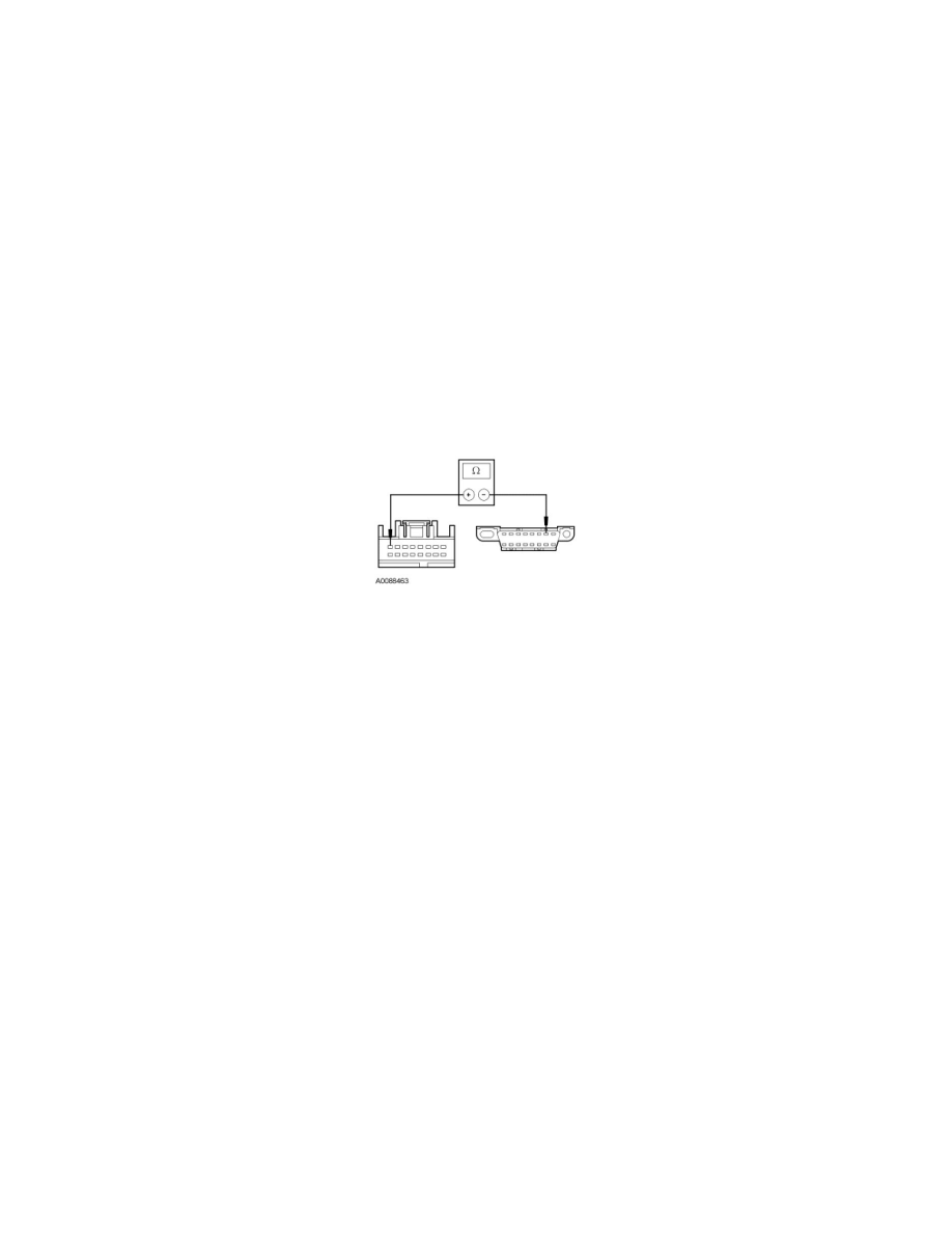
R7 CHECK THE ISO 9141 COMMUNICATIONS NETWORK CIRCUIT BETWEEN THE PAM AND THE DLC FOR AN OPEN
-
Measure the resistance between the PAM C2023-8, circuit VDB10 (GY), harness side and the DLC C251-7, circuit VDB10 (GY), harness side.
-
Is the resistance less than 5 ohms?
Yes
CONNECT the negative battery cable. GO to R8.
No
REPAIR the circuit. CONNECT the negative battery cable. CLEAR the DTCs. REPEAT the network test with the scan tool.
-------------------------------------------------
R8 CHECK FOR CORRECT PAM OPERATION
-
Disconnect the PAM connector.
-
Check for:
-
corrosion
-
damaged pins
-
pushed-out pins
-
Connect the PAM connector and make sure it seats correctly.
-
Operate the system and verify the concern is still present.
-
Is the concern still present?
Yes
INSTALL a new PAM. CLEAR the DTCs. REPEAT the network test with the scan tool.
No
The system is operating correctly at this time. The concern may have been caused by a loose or corroded connector. CLEAR the DTCs. REPEAT the
network test with the scan tool.
-------------------------------------------------
R9 CHECK FOR CORRECT 4X4 CONTROL MODULE OPERATION