
F 350 2WD Super Duty V8-6.4L DSL Turbo (2009)
Tie Rod: Service and Repair
Tie Rod End - Inner
Tie Rod End - Inner, F-250 and F-350 Rear Wheel Drive (RWD)
Removal and Installation
WARNING: Never loosen, reposition or deform the tie-rod adjusting sleeve aligner bracket. Incorrect positioning of the tie-rod adjusting sleeve
clamps may result in steering linkage binding and loss of vehicle control. Failure to follow this instruction may result in serious personal injury
to the vehicle occupant(s).
1. Place the steering wheel in the straight-ahead position.
2. With the vehicle in NEUTRAL, position it on a hoist.
3. Loosen the outer adjusting sleeve clamp nut.
-
To install, tighten to 55 Nm (41 lb-ft).
4. Remove the inner tie-rod end cotter pin, nut retainer and nut.
-
Discard the cotter pin.
-
To install, tighten to 175 Nm (129 lb-ft).
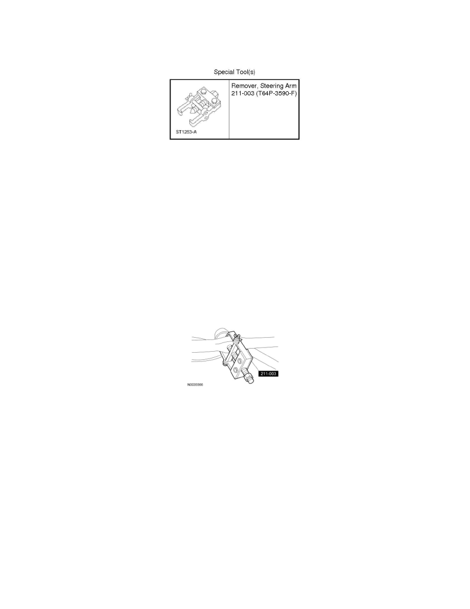
5. Using the Steering Arm Remover, separate the inner tie-rod end from the inner drag link.
6. NOTE: Count the number of turns required to remove the inner tie-rod end and adjusting sleeve for reference during assembly.
Remove the inner tie-rod end and adjusting sleeve as an assembly.
7. Loosen the remaining adjusting sleeve clamp nut.
-
To install, tighten to 55 Nm (41 lb-ft).
8. NOTE: Count the number of turns required to remove the inner tie-rod end for reference during assembly.
Separate the inner tie-rod end from the adjusting sleeve.
9. NOTICE: Make sure that the tie-rod end nut retainer is correctly positioned on the tie-rod end to allow for cotter pin installation. Do not
tighten or loosen the nut to align the retainer slot with the cotter pin hole. Overtightening of the fasteners may result in premature failure
of steering linkage components.
To install, reverse the removal procedure.
-
Install a new cotter pin.
-
Check and if necessary, adjust the toe.