
F 350 4WD Pickup V8-351 5.8L VIN H EFI (1997)
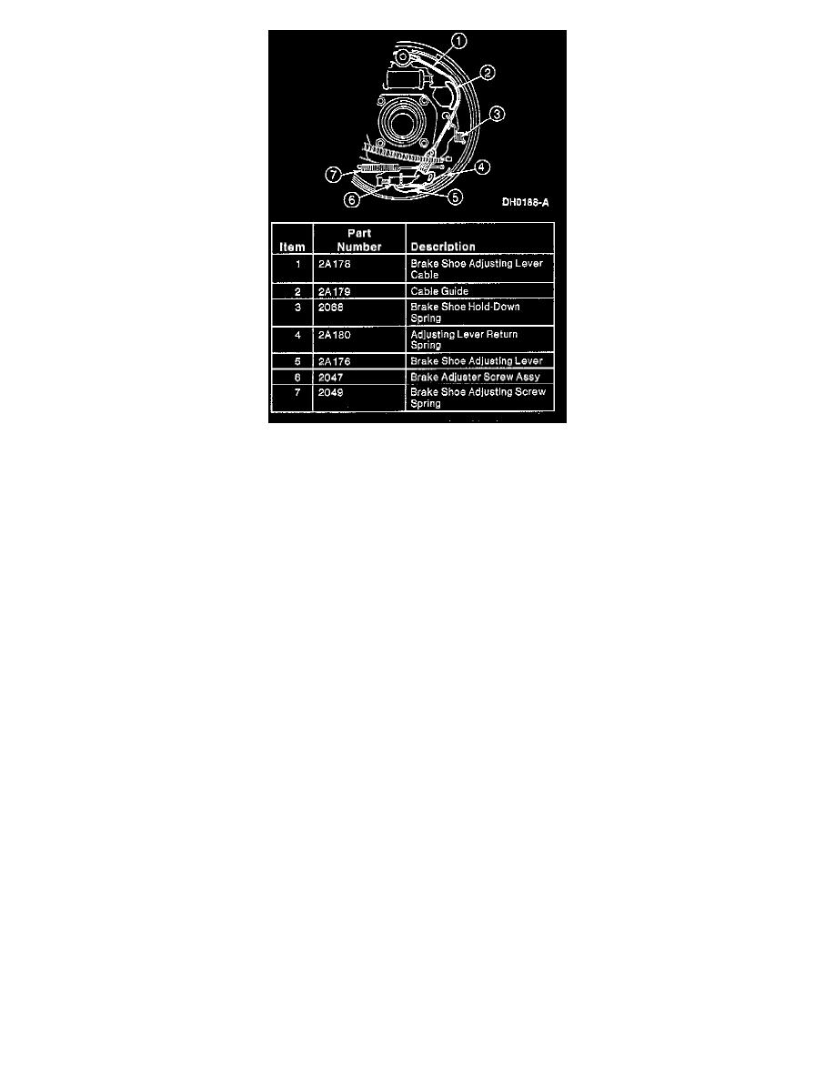
Automatic Adjuster Components
14. Remove brake shoe anchor pin guide plate.
15. Remove the brake shoe hold-down springs, the brake shoe hold-down spring pins and the rear brake shoes and linings.
INSTALLATION
1. Lubricate the brake backing plate friction points. Use Silicone Brake Caliper Grease and Dielectric Compound D7AZ-19A331-A (Motorcraft
WA-10) or an equivalent silicone compound meeting Ford specification ESE-M1C171-A.
2. Position the rear brake shoes and linings and install the brake shoe hold-down spring pins and the brake shoe hold-down springs.
3. Install the brake shoe anchor pin guide plate.
4. Apply Silicone Brake Caliper Grease and Dielectric Compound D7AZ-19A331- (Motorcraft WA-10) or an equivalent silicone compound meeting
Ford specification ESE-M1C171-A and assemble the brake adjuster screw assembly.
NOTE: To prevent incorrect installation, the socket end of each brake adjuster screw is stamped R or L.
5. Position the brake adjuster screw assembly.
6. Install the brake shoe adjusting screw spring.
7. Position the brake shoe adjusting lever cable.
8. Install the cable guide.`