
F 350 4WD Pickup V8-351 5.8L VIN H EFI (1997)
Camshaft: Testing and Inspection
Lobe
Camshaft Installed
Check the lift of each lobe in consecutive order and make a note of the readings.
1. Remove valve cover.
2. Remove rocker arm fulcrum bolts, rocker arm seat and rocker arm.
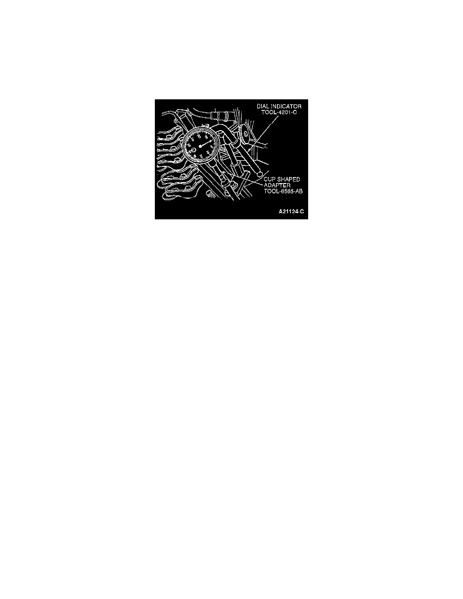
3. Make sure valve tappet is seated against cam. Install Dial Indicator with Bracketry TOOL-4201-C and Cup Shaped Adapter TOOL-6565-AB or
equivalents so that ball socket adapter of indicator is on top of valve tappet or push rod and in same plane as valve tappet or push rod movement.
4. Remove spark plug.
5. Connect an auxiliary starter switch in starting circuit. Crank engine with key off. Bump crankshaft over until valve tappet is on base circle of
camshaft lobe. At this point, valve tappet will be in its lowest position. If checking during engine assembly, turn crankshaft using a socket or
ratchet.
NOTE: If checking during engine assembly, turn crankshaft using a socket or ratchet.
6. Zero dial indicator. Continue to rotate crankshaft slowly until valve tappet is in fully raised position (highest indicator reading).
7. Compare total lift recorded on indicator with specifications.
8. To check accuracy of original indicator reading, continue to rotate crankshaft until valve tappet is once again riding on base circle of camshaft
lobe, and read indicator. If indicator does not read zero, repeat Steps 6 through 8.
NOTE: If lift of any lobe is below specified service limits, camshaft and.valve tappets operating on worn lobe(s) must be replaced, as well as any
valve tappet with pitting or contact face worn flat or concave.
9. Remove dial indicator and auxiliary starter switch.
10. Install valve cover.
CAUTION: After installing rocker arms, do not rotate crankshaft until valve tappets have had sufficient time to bleed down. To do otherwise can
cause serious valve damage. Manually bleeding down will reduce waiting time.
11. Install spark plugs.
Camshaft Removed
1. Clean and inspect the camshaft.
2. Install the camshaft on the lathe or camshaft grinder centers.
3. Position the dial indicator which comes with the machine at the heel of the cam that you are going to check.
4. Zero the dial indicator.
5. Slowly turn the camshaft until the point of the dial indicator is on the tip of the cam.
6. Read the dial indicator. This is your cam lobe lift.
7. Check the lobe lift against the specifications. If any cam is excessively worn, the camshaft and valve tappet will have to be replaced.
Lobe Lift Inspection
1. Inspect camshaft.
2. Measure the distance of each cam at the major diameter.
3. Measure the distance of each cam at the minor diameter.
4. For each cam, subtract the minor diameter from the major diameter. The result for each lobe is the lobe lift.
5. Check the lobe lift for each cam against the specifications.