
F 350 4WD Pickup V8-351 5.8L VIN H EFI (1997)
Connecting Rod Bearing: Component Tests and General Diagnostics
Bore Gauge Method
1. Install bearings in the cylinder block and bearing caps.
2. Install crankshaft and tighten main bearing cap bolts to the specified torque.
3. Remove bearing caps and crankshaft.
4. Reinstall bearing caps with bearings still installed in cylinder block and caps.
5. Tighten bearing cap bolts to torque specified.
6. Using micrometer, measure main bearing journals.
7. Using bore gauge, measure the inside diameter of each bearing assembly. It might be necessary to measure the outer bearings first; then remove
those caps and measure the inner bearings.
8. Subtract the maximum measurement for each journal from the minimum measurement of each bearing to determine the minimum oil clearance.
Allowable clearance is 0.020-0.066 mm (0.0008-0.0026 inch).
Plastigage Method
1. Clean crankshaft journals. Inspect journals and thrust faces for nicks, burrs or roughness that would cause premature bearing wear. When replacing
standard bearings with new bearings, it is good practice to fit bearing to minimum specified clearance. If desired clearance cannot be obtained with
a standard bearing, try a 0.050 mm (0.002-inch) undersize bearing set to obtain proper clearance.
2. If fitting main bearing in-vehicle, position a jack under counterweight adjoining bearing which is being checked. Support crankshaft with jack so
its weight will not compress Plastigage(R) D81L-6002-B or equivalent and provide an erroneous reading.
CAUTION: Do not position jack under crankshaft pulley. Crankshaft post damage will result.
3. Place a piece of Plastigage(R) D81L-6002-B or equivalent on bearing surface across full width of bearing cup and about 6.35 mm (1/4 inch) off
center.
4. Install cap and tighten bolts to specification. Do not turn crankshaft while Plastigage(R) is in place.
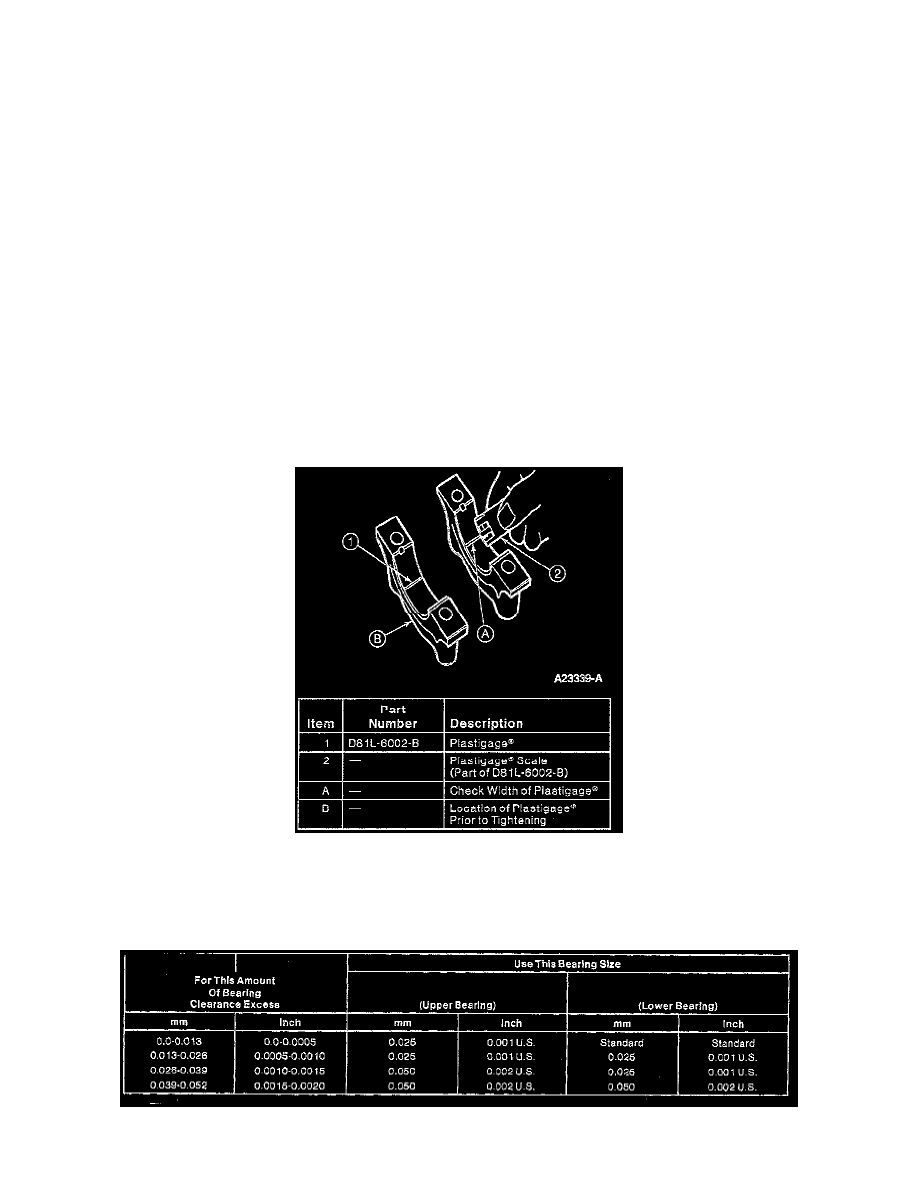
5. Remove cap. Using Plastigage(R) scale, check width of Plastigage(R) at widest point to get minimum clearance. Check at narrowest point to get
maximum clearance. Difference between reading is taper of journals.
6. If bearing clearance exceeds the specified limits try using one of the various combinations of undersize bearings as directed by the accompanying