
F 350 4WD Pickup V8-351 5.8L VIN H EFI (1997)
Connecting Rod: Service and Repair
REMOVAL
1. Drain the cooling system. Drain the crankcase. Remove the intake manifold, cylinder heads, oil pan and oil pump.
2. Remove any ridges and/or deposits from the upper end of the cylinder bores as follows:
Turn the crankshaft until the piston to be removed is at the bottom of its travel, then place a cloth on the piston head to collect the cuttings.
Remove the cylinder ridge with a ridge cutter. Follow the instructions furnished by the tool manufacturers. Never cut into the ring travel area in
excess of 0.794 mm (1/32 inch) when removing ridges.
3. Make sure all connecting rod caps are marked so that they can be installed in their original positions.
CAUTION: Connecting rod caps must be installed in their original locations.
4. Turn the crankshaft until the connecting rod being removed is down.
5. Remove the connecting rod nuts and cap.
6. Push the connecting rod and piston assembly out the top of the cylinder with the handle end of a hammer. Avoid damage to the crankshaft journal
or the cylinder wall when removing the piston and rod assembly.
7. Remove the bearing inserts from the connecting rods and caps.
INSTALLATION
1. If new piston rings are to be installed, remove the cylinder wall glaze. The small depression on the ring designates the top.
2. Install rings using a piston ring installation tool of the proper size.
3. Oil the piston rings pistons and cylinder walls with recommended quality engine oil. The connecting rod and bearing caps are numbered from 1 to
4 in the right bank and from 5 to 8 in the left bank, beginning at the front of the engine. The numbers on the connecting rod and bearing cap must
be on the same side when installed in the cylinder bore. If a connecting rod is ever transferred from one cylinder block or cylinder to another, new
connecting rod bearings should be fitted and the connecting rod should be numbered to correspond with the new cylinder number. When installing
the piston and connecting rod assembly, the largest chamfer at the bearing end of the rod should be positioned toward the crank pin thrust face of
the crankshaft.
NOTE: Be sure to install the pistons in the same cylinders from which they were fitted.
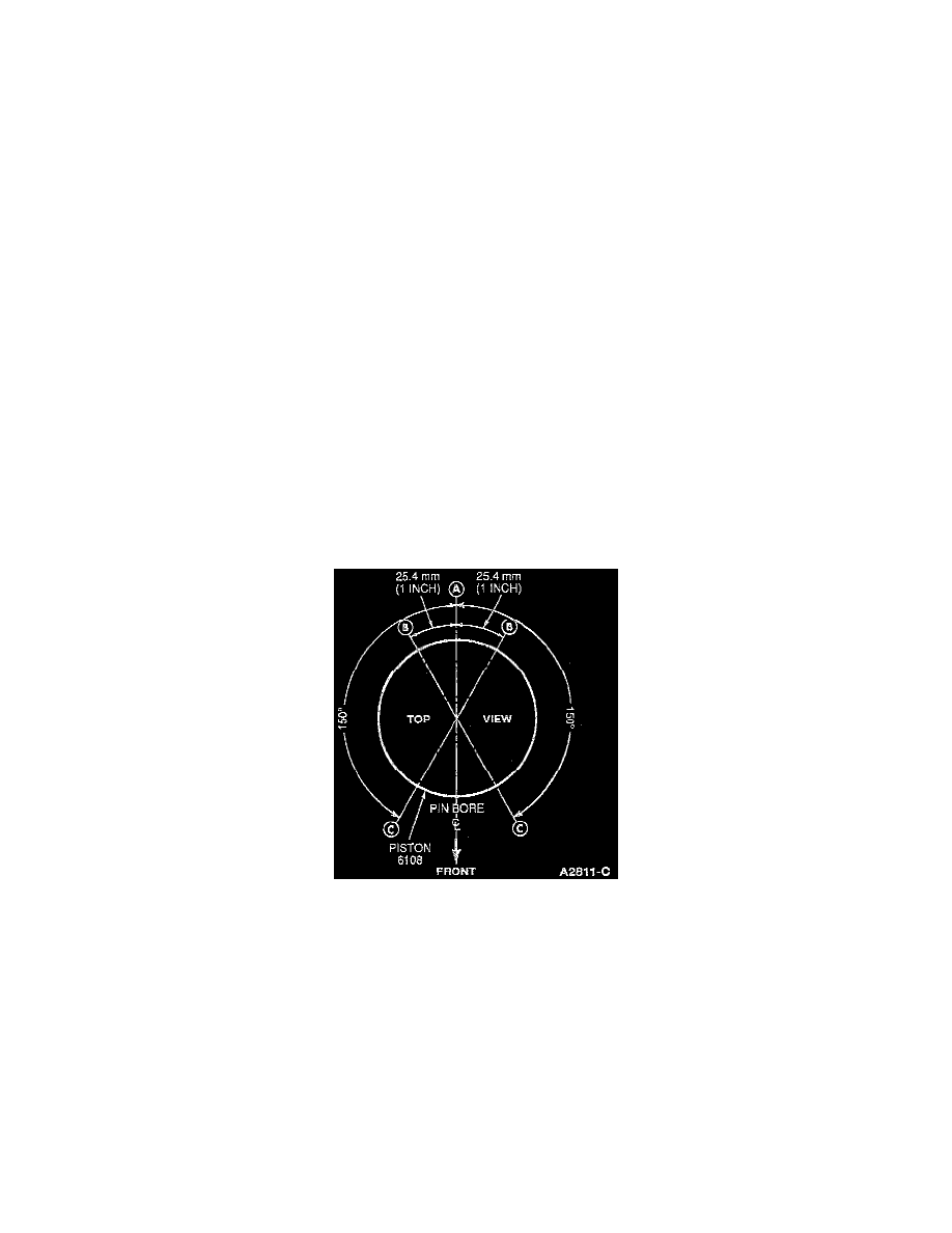
4. Make sure the ring gaps (oil ring spacer-A, oil ring-B, compression ring-C) are properly spaced around the circumference of the piston.
5. Install Piston Ring Compressor D81 L-6002-C or equivalent on the piston and push the piston in with a hammer handle until it is slightly below
the top of the cylinder. Be sure to guide the connecting rods to avoid damaging the crankshaft journals. Install the piston with the indentation notch
in the piston head toward the front of the engine.
NOTE: Replacement pistons are slightly lighter in weight. Pistons must be replaced as a complete set to avoid the introduction of torsional
vibration to the engine.
6. Install connecting bearings and check the clearance of each connecting rod bearing.
7. After the connecting rod bearings have been fitted, apply a light coat of recommended engine oil to the journals and connecting rod bearings.
8. Turn the crankshaft throw to the bottom of its stroke. Push the piston all the way down until the connecting rod bearing seats on the crankshaft
Journal.
9. Install the connecting rod cap. Tighten the nuts to 54-61 Nm (40-45 ft. lbs.).