
F 350 4WD Pickup V8-351 5.8L VIN H EFI (1997)
18. Remove oil baffle from inner bearing cup bore. Oil baffle is located between the inner bearing cup and carrier bore. Shims are located between the
inner bearing cup and baffle. Do not damage the shims when removing the bearing cup.
NOTE: If any shims are damaged, measure the thickness and replace with shims of equal thickness.
19. Turn nose of carrier downward and remove outer pinion bearing cup using a suitable pinion bearing cup remover and driver handle. Pass bearing
cup remover and drive handle through inner bearing cup bore and place against outer bearing cup, then drive outer bearing cup out of bore.
20. Remove differential case bearings and shims from case. Position step plate tool No. D80L-630-4, or equivalent, under bearing, then install
universal bearing remover tool No. D81L-4220-A, or equivalent, and remove bearing. Turn case over and remove other bearing in the same
manner.
21. Wire shims, bearing cup and cone together and identify from which side of differential case they were removed.
NOTE: If any shims are damaged, replace with new shims. It is recommended that bearings be replaced.
22. Place a few shop towels over a vise to prevent ring gear teeth from being nicked after it is free from case assembly. Remove ring gear bolts. Tap
ring gear with a rawhide or plastic hammer to free it from case. Remove case and ring gear from vise.
NOTE: Whenever removing ring gear bolts, discard and replace with new bolts upon assembly.
23. Remove bearing and oil slinger from drive pinion using tool No. D81L-4220-A, or equivalent. For controlling drive pinion depth, an oil slinger
with a selective thickness is used.
NOTE: If oil slinger is damaged, measure thickness and replace with a slinger of equal thickness.
24. Inspect all parts for damage and replace as required.
Model 60 Monobeam
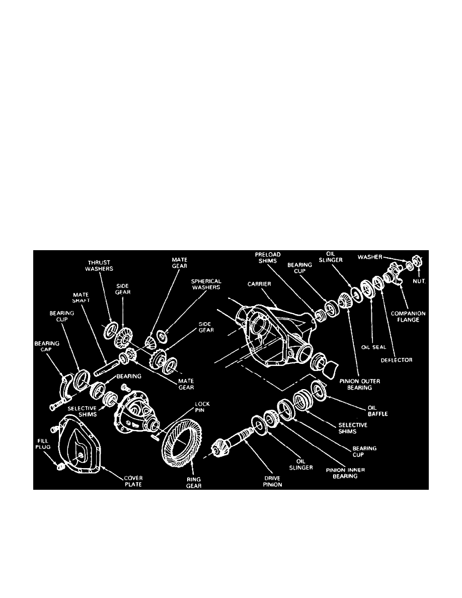
Fig. 5 Exploded View Of Model 60 Monobeam Axles
1. Remove axle from vehicle, please refer to Transmission and Drivetrain/Drive Axles, Bearings and Joints/Axle Shaft Assembly/Axle Shaft/Service
and Repair/ See: Drive Axles, Bearings and Joints/Axle Shaft Assembly/Axle Shaft/Service and Repair
2. Remove axle shafts from axle.
3. Remove cover plate and drain lubricant, then clean all gasket surfaces.
4. Remove bearing caps. Note matched numbers or letters stamped on the cap and carrier assembly. These numbers or letters must be matched during
assembly. These numbers may either be stamped vertically, horizontally or in some instances both vertically or horizontally.
5. Mount spreader tool No. 4000-E and spreader adapter tool No. T80T-4000-B, or equivalents, onto carrier assembly.