
F 350 4WD Pickup V8-351 5.8L VIN H EFI (1997)
Differential Case: Service and Repair
Removal & Installation
REMOVAL
1. Raise the vehicle on a twin-post hoist.
2. Remove the front wheels (1007) and tires from the vehicle.
3. CAUTION: After removal, the disc brake caliper (2B120) must be wired to the spring or otherwise supported to prevent suspending the disc
brake caliper by the flexible hose. Allowing the disc brake caliper to hang by the flexible hose could result in brake line failure. If suspension of
the disc brake caliper is not practical, remove it.
Remove the brake caliper from the rotor.
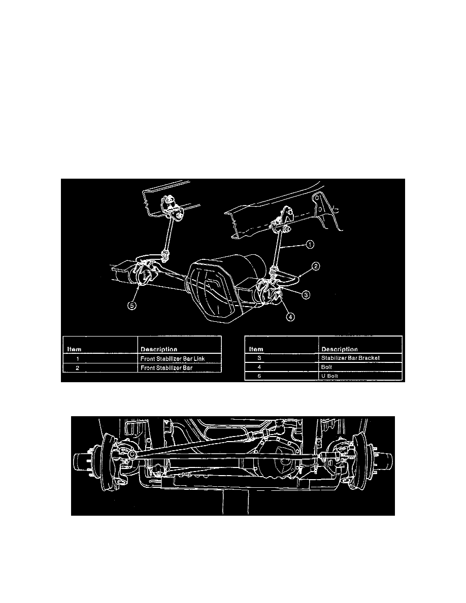
4. Remove the washers and nuts securing the front stabilizer bar links (5K483) to the front stabilizer bar (5482). Disconnect the front stabilizer bar
links from the front stabilizer bar.
5. If required, remove the U-bolts and bolts and nuts retaining the front stabilizer bar and stabilizer bar brackets (5486) to the axle and remove the
front stabilizer bar.
6. Remove the cotter pins and castellated nuts securing the connecting rod and tie rod end to the steering knuckles. Separate the connecting rod and
tie rod end from the steering knuckles using Pitman Arm Puller T64P-3590-F. Wire the steering linkage to the spring.
7. Remove the two nuts and U-bolts from the front driveshaft U-joint flange.
8. NOTE: Mark yoke and driveshaft with a marking paint pen for assembly in the same position.
Disconnect the driveshaft from the front axle pinion flange. Securely wire the driveshaft to the frame.