
F 350 4WD Pickup V8-460 7.5L (1984)
Intake Manifold: Service and Repair
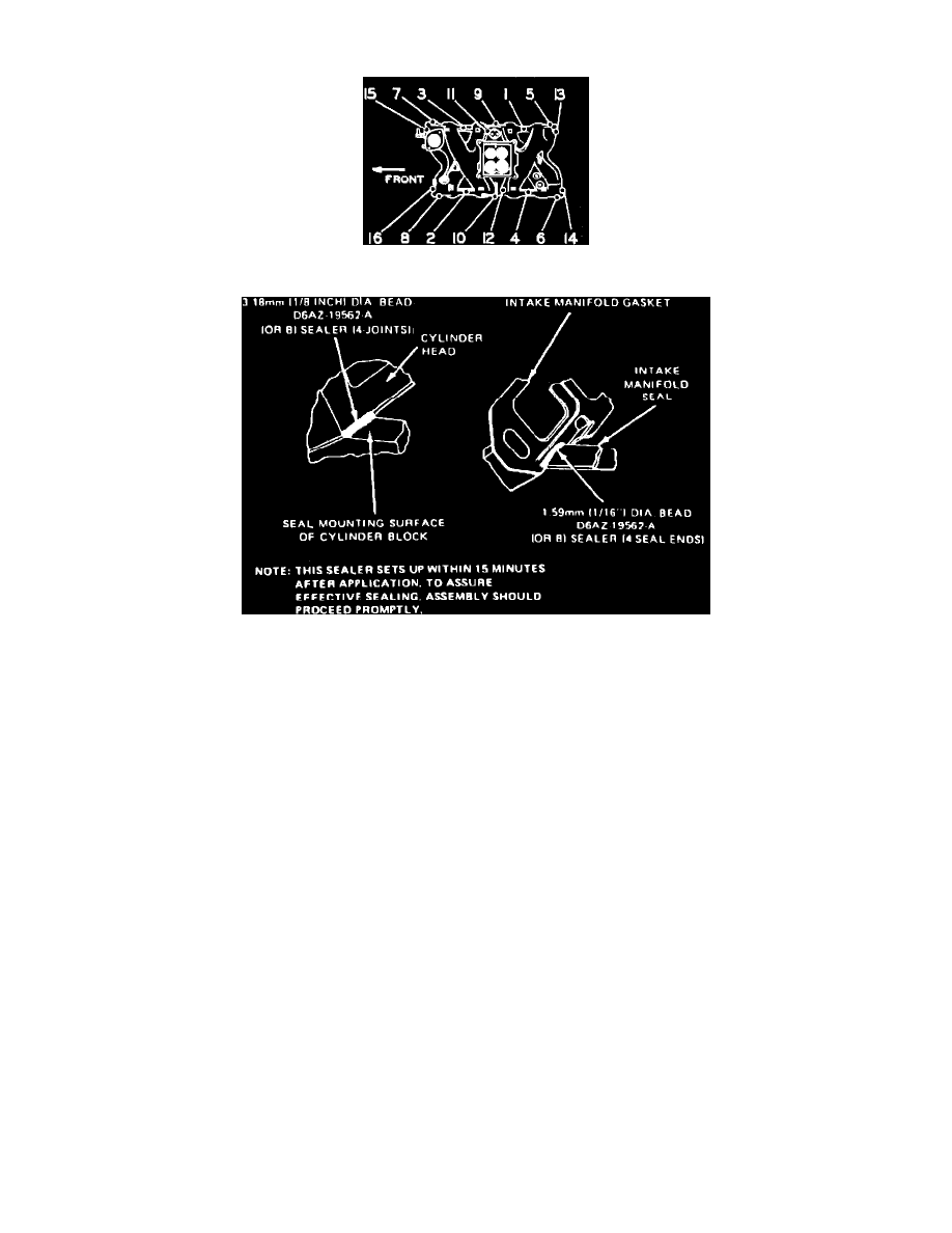
Fig. 12 Intake manifold tightening sequence. V8-460
Fig. 20 Intake manifold installation. V8 engines
V8-460
1.
Drain cooling system, then remove air cleaner and intake duct assembly.
2.
Disconnect upper radiator hose from engine and the heater hose from intake manifold and water pump and position aside.
3.
Loosen water pump bypass hose clamp at intake manifold.
4.
Disconnect PCV valve hose from right rocker arm cover.
5.
Disconnect and tag all vacuum lines at rear of intake manifold.
6.
Disconnect ignition wires from spark plugs and position aside.
7.
Disconnect high tension lead from ignition coil, then remove distributor cap and wires as an assembly.
8.
Disconnect and tag all distributor vacuum lines at carburetor and vacuum control valve.
9.
Disconnect accelerator linkage and transmission kickdown linkage (if equipped).
10.
On models equipped with speed control, remove speed control linkage bracket from intake manifold and disconnect it from carburetor.
11.
On all models, remove accelerator linkage cable attaching bolts and position linkage aside.
12.
Disconnect fuel inlet line from carburetor.
13.
Disconnect electrical connector from ignition coil battery terminal.
14.
Disconnect engine temperature and oil pressure sending unit electrical connectors and any other connectors necessary for intake manifold removal.
15.
Unfasten wiring harness from 3 retaining clips on left rocker arm cover and position harness aside.
16.
Remove ignition coil and bracket assembly.
17.
Remove intake manifold attaching bolts and nuts, then the intake manifold and carburetor as an assembly.
18.
Reverse procedure to install. Apply sealer as shown in Fig. 20 Torque manifold attaching bolts to 22-32 ft-lbs as shown in Fig. 12.