
F 350 4WD Pickup V8-7.3L DSL (1988)
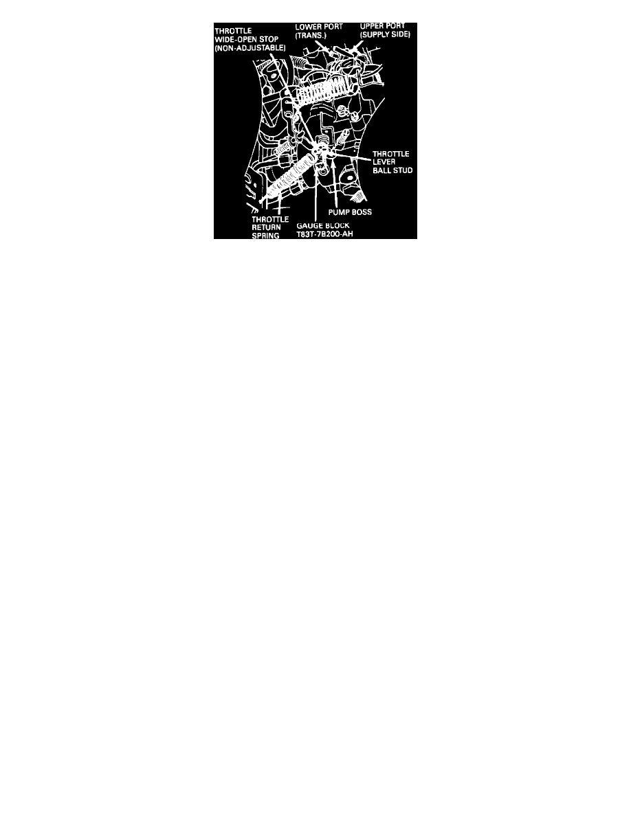
Figure 5
5.
C6 Automatic Transmission Only:
Check adjustment of the Vacuum Regulator Valve (VRV). Refer to Figures 4 and 5. On these trucks, a VRV provides a vacuum signal which is
proportional to the throttle position, to the transmission vacuum diaphragm. To check the VRV for proper operation and adjustment, the engine must not
be running. Proceed as follows:
a.
Disconnect the two-port vacuum connector from the VRV located on the left side of the fuel injection pump, see Figure 4.
b.
Remove the throttle return cable from the throttle lever on the right side of the fuel injection pump.
c.
Remove the throttle cable return springs. Install the end of the spring over the throttle lever ball stud and the other end over the throttle cable
support bracket.
d.
Attach a vacuum pump with gauge to the upper port of the VRV (the vacuum supply side).
e.
Attach a vacuum gauge to the lower port of the VRV (labeled TRANS on the VRV).
f.
Apply 20 inches of Hg minimum of vacuum to the VRV and maintain it. It will be necessary to pump vacuum up as it bleeds off. CYCLE THE
THROTTLE LEVER FIVE (5) TIMES FROM IDLE TO WIDE OPEN THROTTLE (WOT) WITH VACUUM APPLIED. Insert gauge block,
T83T-7B200-AH (0.515 inch), between the pump boss and the throttle wide-open stop, Figure 5. The throttle return spring, as repositioned in step
c above, will hold the throttle lever stop against the gauge block. THE VACUUM GAUGE ATTACHED TO THE LOWER PORT OF THE VRV
SHOULD INDICATE 6-8 INCHES OF VACUUM. IF THE VACUUM READING IS WRONG. ADJUST THE VRV TO OBTAIN READINGS
OF 7 INCHES OF VACUUM.
g.
To adjust the VRV, loosen the two screws that attach the VRV to the fuel injection pump, Figure 4. Rotate the VRV until proper vacuum is
obtained. When you get the proper vacuum reading, tighten the two screws to 75-90 lb.in. (8-10.5 N-m). If the VRV can't be adjusted to get the
proper vacuum, replace the VRV and repeat this procedure starting at step d.
h.
Remove the gauge block.
i.
Reattach the throttle return spring and the throttle cable.
j.
Apply 20 inches of vacuum to the VRV and WHILE MAINTAINING VACUUM, CYCLE THE THROTTLE LEVER FROM IDLE TO WOT
FIVE (5) TIMES. The vacuum gauge must indicate at least 13 inches with the throttle at the idle position. If the vacuum gauge indicates less than
13 inches, the VRV must be replaced and the new VRV adjusted per the above procedure.
k.
After making the check or adjustment, remove the vacuum pump and gauge from the VRV and reattach the vacuum connector.
l.
Start the engine. Check the throttle operation and transmission.
E40D Automatic Transmission Only:
6.
E40D Automatic Transmission Only: Perform the EEC-IV Quick Test per the 1989 Engine/Emissions Diagnosis Shop Manual, Volume H, Section
14. This includes the diagnosis and correction of any codes output during the Quick Test. The failure or misadjustment of sensors used for or with