
F 350 4WD Pickup V8-7.3L DSL (1988)
30.
Install Bracket B on the drag link of the steering linkage as shown in drawing Attachment 7, Fig. 4, leaving the nuts loose.
31.
Turn the wheels all the way to the right and be sure they are held there (Use an assistant to turn and hold the steering wheel or turn the ignition
switch on, then turn the steering yourself all the way to the right and turn the key to the off position to lock the wheels in a full right turn). Check to
see that the right hand spindle steering stop is in contact with the axle steering stop behind the lower ball joint. Install the shock rod end of the
steering damper to bracket B as. shown in drawing Attachment 8, Fig. 5. Torque the steering damper shock to bracket B nut to 74-88 N-m (55-65
ft.lbs.).
32.
Adjust bracket B along the drag link so that 1/2 inch of the steering amper shock rod is extended. (TIGHTEN THE U-BOLT NUTS THAT
ATTACHES BRACKET B TO DRAG LINK TO 20-24 N-m 15-18 FT.LBS.).
NOTE:
PLEASE USE A TORQUE WRENCH ON THE "U" BOLT NUTS. IMPROPER TORQUE OF "U" BOLTS COULD LEAD TO
LOOSENING OF BRACKET "B" AND A SHIMMY CONDITION. BE SURE THE MOUNTING FLANGE OF BRACKET B IS
VERTICAL AS SHOWN IN DRAWING ATTACHMENT 8, FIG. 6.
33.
Turn wheels all the way to the left (using the same procedure as in step 31) to be sure the steering damper shock does not bottom out. The steering
damper shock rod length should be between 7-1/2 and 8 inches with the wheels locked in full left turn as shown in drawing Attachment 8. If the
rod length is not between 7-1/2 and 8 inches, then loosen the U-bolt nuts and slide bracket B, (drawing Attachment 8, Figure 6) along the drag link
until the rod length is between 7-1/2 and 8 inches. Retorque the U-bolt nuts to 20-24 N-m (15-18 ft.lbs.). As a final check, turn the wheels to full
right turn to be sure the steering damper shock does not bottom out.
34.
Lower vehicle to shop floor. With the weight of vehicle on the suspension, tighten pivot bushing bolt and nut to 163-203 N-m (120-150 ft.lbs).
Recheck all nuts for tightness.
FRONT END ALIGNMENT AND ROAD TEST:
35.
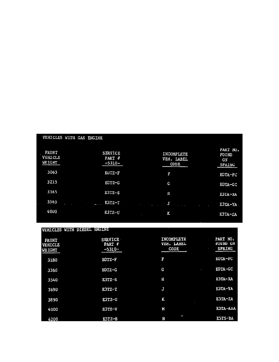
To determine if front springs are correct for vehicle, the front springs installed on vehicle must be verified for capacity. Loads in excess of the
spring rated capacity will increase caster due to low ride height. Measure front ride height (measure between bottom of spring tower and top of