
F 350 4WD Pickup V8-7.3L DSL Turbo VIN F (1994)
18
2041
Brake Adjuster Screw
19
2200
Primary Shoe Lining
20
2068
Brake Shoe Hold Down Spring
21
2200
Primary Shoe
22
2296
Brake Shoe Retracting Spring
23
2A178
Brake Shoe Adjusting Lever Cable
24
2092
Brake Adjusting Hole Cover
25
2069
Brake Shoe Hold Down Spring Pin
INSTALLATION
1. Clean the ledge pads on the brake backing plate.
2. Apply a lithium-base grease, Premium Long-Life Grease XG-1-C or -K (ESA-M1C75-B) or equivalent or Disc Brake Caliper Lubricant
D7AZ-19590-A (ESA-M1C172A) or equivalent to the contacts of the brake shoe retracting spring and the brake shoe hold down spring on the rear
brake shoes and linings and brake backing plate.
3. Apply a lithium-base grease, Premium Long-Life Grease XG-1-C or -K (ESA-M1C75-B) or equivalent or Disc Brake Caliper Lubricant
D7AZ-19590-A (ESA-M1C172A) or equivalent to the threads and socket end of the brake adjuster screw.
4. Install the upper brake shoe retracting spring on the primary and secondary rear brake shoes and linings as shown above.
5. Position the rear brake shoe and lining on the brake backing plate with the push rods of the rear wheel cylinder in the slots of the rear brake shoe
and lining.
6. Install the brake shoe hold down springs. Use Hold Down Spring Tool T73T-2300-A.
7. Install the brake adjuster screw with the slot in the head of the brake adjuster screw toward the primary rear brake shoe and lining.
8. Install the lower brake shoe retracting spring, adjusting lever return spring, adjusting lever assembly (part of brake shoe adjusting lever kit), and
connect the rear parking brake cable to the adjusting lever.
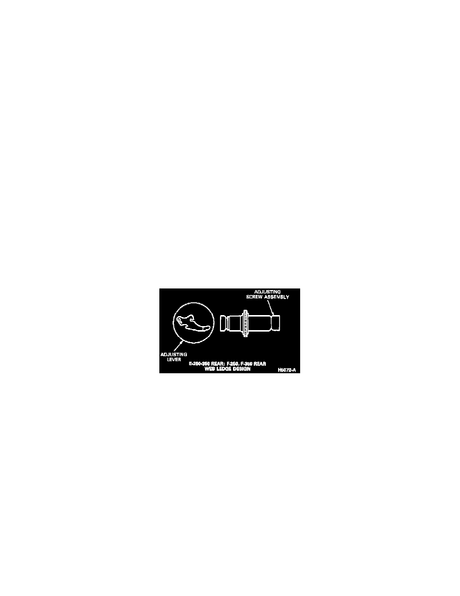
Brake Adjusting Screw
NOTE: Install the brake adjuster screws in the same locations from which they were removed. Interchanging them from one side of the vehicle to
the other will cause the rear brake shoes and linings to retract rather than expand each time the automatic adjusting mechanism is operated. To
prevent incorrect installation, the socket end of each adjusting screw is stamped with an R or L to indicate their installation on the right or left side
of the vehicle. The adjusting pivot nuts can be distinguished by the number of lines machined around the body of the nut. Two lines indicate a
right-hand nut; one line indicates a left-hand nut.
9. Position the brake shoe adjusting lever cable in the cable guide and install the cable anchor fitting on the anchor pin.
10. Install the rear parking brake cable in the anchor pin and washer and secure with the retaining nut behind the brake backing plate.
11. Adjust the brakes before installing the brake drums.