
F 350 4WD Super Duty V10-6.8L (2002)
Compressor Clutch: Description and Operation
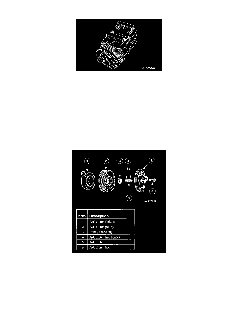
A/C compressor and Clutch Assembly
NOTE:
^
Internal A/C compressor components are not serviced separately. The FS-10 A/C compressor is serviced only as an assembly. The A/C clutch,
A/C clutch pulley, A/C clutch field coil and the shaft seal are serviceable.
^
Whenever the A/C compressor is replaced due to a failure that produces debris in the system, also replace the suction accumulator and the A/C
evaporator core orifice.
The FS-10 A/C compressor has the following characteristics:
^
A ten-cylinder swashplate design utilizing the tangential design mount.
^
A one-piece lip-type seal (replaceable from the front of the A/C compressor) is used to seal it at the shaft opening in the assembly.
^
Five double-acting pistons operate within the cylinder assembly. The pistons are actuated by a swashplate that changes the rotating action of the
shaft to a reciprocating force.
^
Reed-type discharge valves are located between the cylinder assembly and the head at each end of the A/C compressor.
^
The A/C compressor uses PAG Refrigerant Compressor Oil (R-134a Systems) or equivalent. This oil contains special additives required for the
A/C compressor.
Compressor Clutch Components
The magnetic A/C clutch has the following characteristics:
^
It drives the compressor shaft.
^
When battery positive voltage (B+) is applied to the A/C clutch field coil, the clutch plate and hub assembly is drawn toward the A/C clutch
pulley.
^
The magnetic force locks the clutch plate and hub assembly and the A/C clutch together as one unit, causing the compressor shaft to rotate.
^
When B+ is removed from the A/C clutch field coil, springs in the clutch plate and hub assembly move the clutch plate away from the A/C clutch
pulley.