
F 350 4WD Super Duty V10-6.8L (2002)
Power Take-Off: Description and Operation
POWER TAKE-OFF SWITCH AND CIRCUIT
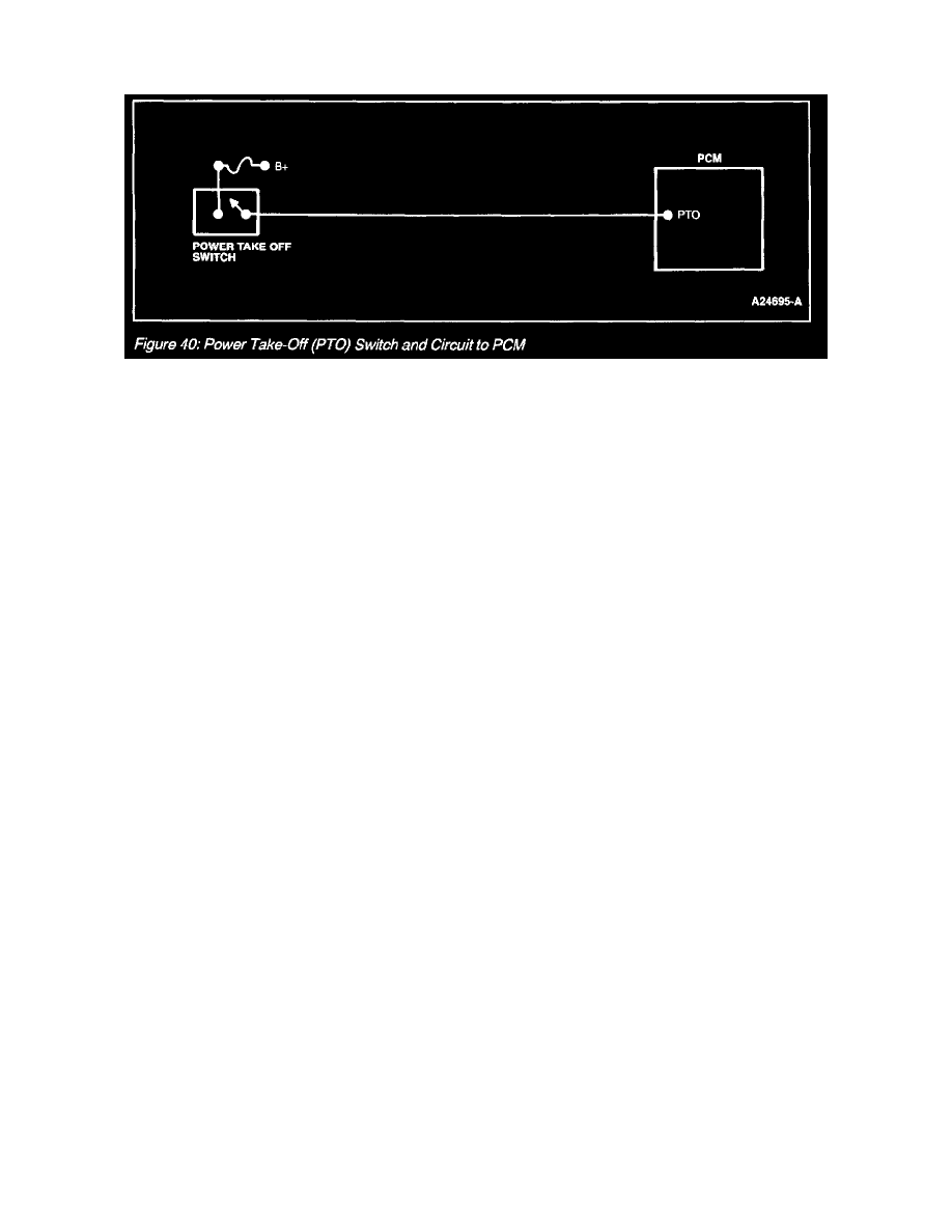
Power Take-Off (PTO) Switch and Circuit To PCM
The Power Take-Off (PTO) circuit (Figure 40) is used by the PCM to disable some of the OBD II Monitors during PTO operation. The PTO circuit
normally carries low voltage. When the PTO switch is on/closed, B+ is supplied to the PTO input circuit indicating to the PCM that an additional load
is being applied to the engine. If this action was not reported by the PTO circuit, a false Diagnostic Trouble Code may be stored.