
F 350 4WD Super Duty V10-6.8L VIN V (2005)
6. Disconnect the upper radiator hose from the thermostat housing.
7. Disconnect the heater coolant hose from the coolant crossover assembly.
8. Disconnect the intake manifold runner control (IMRC) actuator electrical connector.
9. Disconnect the fuel rail pressure and temperature sensor electrical connector and vacuum connector.
10. Disconnect the 10 fuel injector electrical connectors.
11. Disconnect the positive crankcase ventilation (PCV) tube quick connect coupling from the intake manifold.
12. Disconnect the quick connect couplings and remove the evaporative emissions (EVAP) tube.
13. Disconnect the brake booster vacuum hose from the intake manifold.
14. Disconnect the 2 heated PCV coolant hoses from the intake manifold.
15. Disconnect the throttle position (TP) sensor and electronic throttle control electrical connectors.
16. Disconnect the engine wiring harness position retainers from the intake manifold.
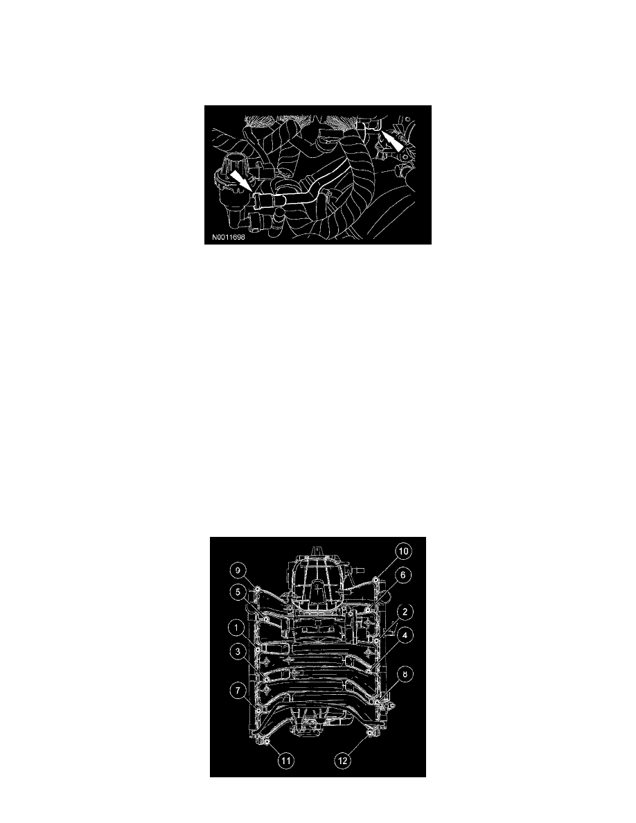
17. Remove the 12 intake manifold bolts.
18. CAUTION: Do not use metal scrapers, wire brushes, power abrasive discs or other abrasive means to clean the sealing surfaces. These tools
cause scratches and gouges which make leak paths. Use a plastic scraping tool to remove all traces of old sealant.
Remove the 2 bolts, the coolant bypass Cube and discard the gaskets.
^
Clean and inspect the sealing surfaces with metal surface prep. Follow the directions on the packaging.
19. CAUTION: Do not use metal scrapers, wire brushes, power abrasive discs or other abrasive means to clean the sealing surfaces. These tools
cause scratches and gouges which make leak paths. Use a plastic scraping tool to remove all traces of old sealant.
Remove the intake manifold and discard the gaskets.
^
Clean and inspect the sealing surfaces with metal surface prep. Follow the directions on the packaging.
Installation
1. Using new intake manifold gaskets, position the intake manifold.
2. Using new gaskets, position the coolant crossover and install the 2 bolts
^
Tighten to 25 Nm (18 ft. lbs.).