
F 350 4WD Super Duty V10-6.8L VIN V (2005)
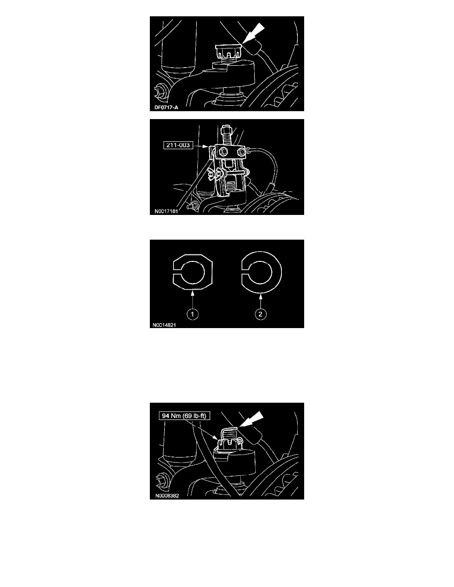
8. Remove the castellated nut from the upper ball joint.
9. Using the special tool, remove the existing LH and RH adjuster sleeves. All vehicles are built by the assembly plant with a non-adjustable
camber/caster sleeve.
1
Service adjusters have an eight-sided flange with the camber/caster adjustment range stamped into the bottom (0 degree, 1/4 degree, 1/2
degree, 3/4 degree or 1 degree).
2
Production adjusters have a round flange with a flattened edge. The amounts of pre-set camber and caster are stamped into the top of the
adjuster.
10. Install interim 0 degree service adjusters to both sides of the vehicle.
11. Install the castellated nut to the upper ball joint.
12. Install the front wheel(s) and check caster and camber readings with the 0 degree service adjusters installed.
13. Calculate the maximum amount of camber and/or caster adjustment required to achieve the optimal settings, as provided in the Alignment
Specifications table, by subtracting the measured values from the optimal target values.
Example: For a 4x4 F350 P/U (pickup) with Single Rear Wheels (SRW),
^
Optimal camber spec target = 0.15 ± 0.75.
^
Optimal caster spec target = 2.5 ± 1.2.