
F 350 4WD Super Duty V10-6.8L VIN Y (2006)
6. NOTE: If excessive force must be used during brake rotor removal, the brake rotors should be checked for lateral runout prior to installation.
Remove the 8 wheel extension nuts and the wheel extension.
All vehicles
7. CAUTION: Do not allow the caliper to hang from the brake hose or damage to the hose can occur.
Remove the 2 caliper anchor plate bolts and position the caliper assembly aside.
^
Support the caliper using mechanic's wire.
8. Index mark and remove the brake disc.
9. CAUTION: Due to the fit of the splines, the hub lock will be difficult to remove. Lifting or lightly prying (with a small bar) on the axle U-joint
will ease removal. When prying on the cap/hub flange, work around the flange to uniformly withdraw the hub lock.
CAUTION: The service replacement kit includes 2 O-ring seals; one for testing the hub lock assembly and one for reassembly into the wheel hub
. DO NOT RE-USE O-RING SEALS.
CAUTION: Always check the vacuum leak rate of the wheel end assembly when repairing or diagnosing the axle, wheel end or hub lock
performance.
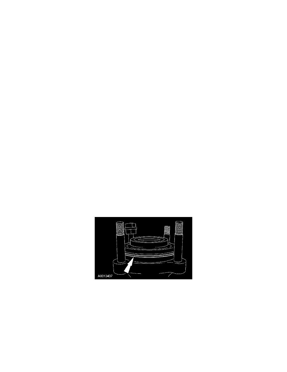
Remove the wheel hub lock.
^
Loosen each retainer screw 1 to 2 turns.
^
Gently pry on the hub lock cap edge to release gasket adhesion.
^
Remove and discard the retainer screws.
^
While lifting/jiggling the axle U-Joint, pull or uniformly pry the hub lock from the wheel hub.
10. Remove the axle shaft snap ring.
11. NOTE: The wheel hub assembly is a slip fit design and should not require a puller to remove it.
Remove the 4 wheel hub assembly bolts and the wheel hub assembly.
12. If necessary, remove the brake disc shield.
Vehicles with ABS
13. Remove the wheel speed sensor bolt and the sensor.
All vehicles
14. Remove and discard the wheel hub assembly O-ring seal.