
F 350 4WD Super Duty V8-5.4L (2009)
-
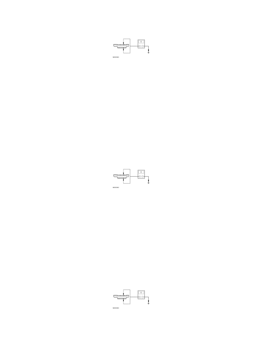
Disconnect: IC C220.
-
Measure the resistance between the DLC C251-6, circuit VDB04 (WH/BU), harness side and ground; and between the DLC C251-14, circuit
VDB05 (WH), harness side and ground.
-
Are the resistances greater than 5,000 ohms?
Yes
CONNECT all modules. CONNECT the negative battery cable. GO to T36.
No
If the vehicle is equipped with a diesel engine, GO to T27.
If the vehicle is not equipped with a diesel engine, REPAIR the circuits. CONNECT all modules. CLEAR the DTCs. REPEAT the network test with the
scan tool.
-------------------------------------------------
T27 CHECK THE HS-CAN (+) AND HS-CAN (-) CIRCUITS FOR A SHORT TO GROUND WITH THE EVRT ACTUATOR
DISCONNECTED
-
Disconnect: EVRT Actuator C1390.
-
Measure the resistance between the DLC C251-6, circuit VDB04 (WH/BU), harness side and ground; and between the DLC C251-14, circuit
VDB05 (WH), harness side and ground.
-
Are the resistances greater than 5,000 ohms?
Yes
CONNECT all modules. CONNECT the negative battery cable. GO to T37.
No
If the vehicle is equipped with a TCM, GO to T28.
If the vehicle is not equipped with a TCM, GO to T29.
-------------------------------------------------
T28 CHECK THE HS-CAN (+) AND HS-CAN (-) CIRCUITS FOR A SHORT TO GROUND WITH THE TCM DISCONNECTED
-
Disconnect: TCM C1750.
-
Measure the resistance between the DLC C251-6, circuit VDB04 (WH/BU), harness side and ground; and between the DLC C251-14, circuit
VDB05 (WH), harness side and ground.
-
Are the resistances greater than 5,000 ohms?
Yes