
F 350 4WD Super Duty V8-6.4L DSL Turbo (2008)
NOTE: The pins mentioned above are not populated.
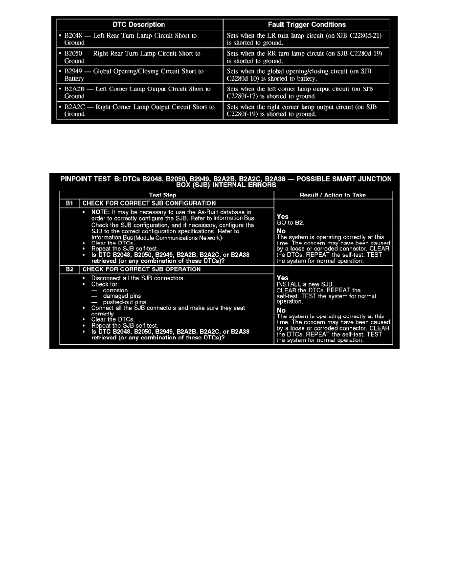
This pinpoint test is intended to diagnose the following:
-
SJB
B1-B2
Upfitter Relay Box
PINPOINT TEST C: THE CUSTOMER ACCESS SYSTEM DOES NOT OPERATE CORRECTLY
Normal Operations
With the ignition key in the ON position, voltage is supplied to the upfitter control switches through circuit CBP42 (GN). Voltage is supplied to the
switched side of the upfitter relays on circuits SBB07 (WH/RD) (upfitter relay No. 1), SBB08 (VT/RD) (upfitter relay No. 2), SBP14 (BN/RD)
(upfitter relay No. 3), or SBP16 (VT/RD) (upfitter relay No. 4). When a control switch is closed it supplies voltage to 1 of the 4 upfitter relays through
circuit CAC01 (GN/BU) (upfitter relay No. 1), CAC02 (GY/BN) (upfitter relay No. 2), CAC03 (WH/VT) (upfitter relay No. 3), or CAC04 (WH/BU)
(upfitter relay No. 4) closing the upfitter relay. When the relay closes, voltage is supplied through the relay to the output circuits (to the blunt cut ends)
of CAC05 (YE) (upfitter relay No. 1), CAC06 (GN/BN) (upfitter relay No. 2), CAC07 (VT/GN) (upfitter relay No. 3), or CAC08 (BN) (upfitter relay
No. 4).
This pinpoint is intended to diagnose the following:
-
Fuse(s)
-
Upfitter relay(s)
-
Upfitter relay switch(es)
-
Wiring, terminals or connectors
-
Upfitter relay box
-
Smart junction box (SJB)
-
Battery junction box (BJB)