
F 350 4WD Super Duty V8-6.4L DSL Turbo (2008)
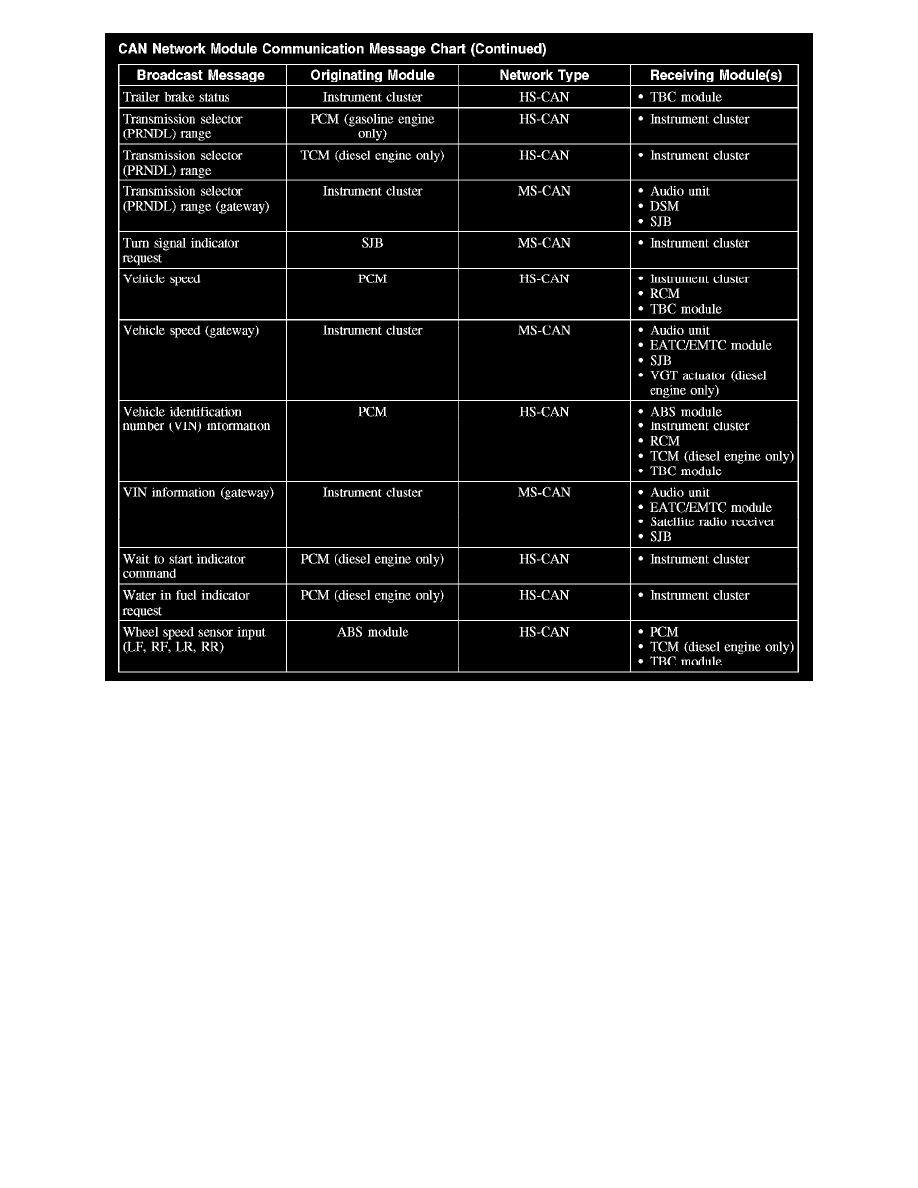
CAN Network Module Communication Message Chart (Part 6)
Inspection and Verification
INSPECTION AND VERIFICATION
This provides step-by-step module configuration procedures. Carry out the PMI procedures when another Vehicle System directs to carry out
configuration or when DTCs from the given list are present. See: Programming and Relearning
Principles of Operation
PRINCIPLES OF OPERATION
Configurable modules accommodate a variety of vehicle options, eliminating the need for many unique modules for one vehicle line. These modules
must be configured when replaced as part of a repair procedure.
Configurable modules should not be exchanged between vehicles since the settings are unique to each vehicle. Failure to configure a new module may
result in improper operation and/or any of the following DTCs setting:
-
B2477 - sets when a body/chassis module is not configured or is configured incorrectly.
-
P0602, P0605 and/or P1639 - sets when the powertrain control module (PCM) vehicle identification (VID) block is not configured.
-
B2900 - sets when there is a VIN mismatch between the module with the B2900 and the PCM. The stored VIN in either module may be incorrect.
-
U0300 - sets when the configuration between 2 or more modules do not match.
-
U2050 and/or U2051 - sets when a valid strategy/calibration is not present.
The following are the 3 different methods of configuration:
-
Programmable module installation (PMI)
-
Module reprogramming ("flashing")
-
Programmable parameters