
F 350 4WD Super Duty V8-6.4L DSL Turbo (2008)
4. Select appropriate wire splice for the wires to be spliced.
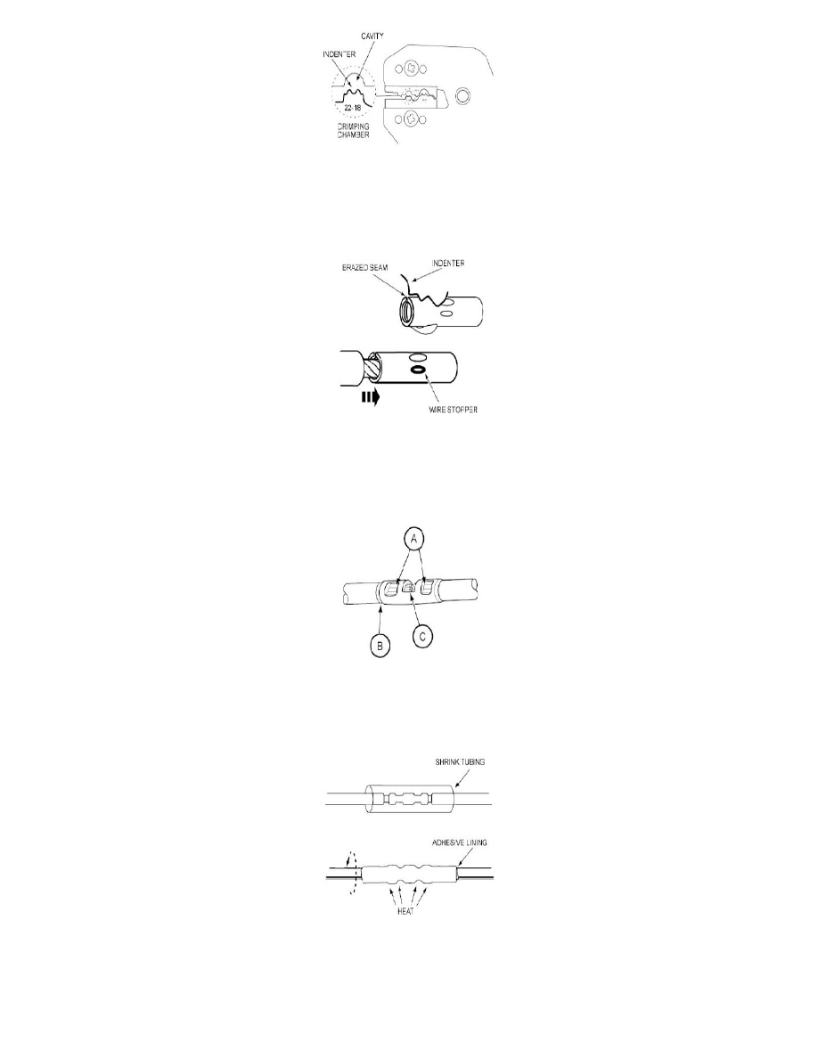
5. Identify the appropriate crimping chamber on the Rotunda 164-R5901 Pro-Crimper by matching the wire size on the dies with the wire size
stamped on the butt splice.
NOTE: Rotunda 164-R5901 Pro-Crimper is the only tool that can be used with these splices.
6. Center one end of the wire splice in the appropriate crimping chamber.
7. If visible, be sure to place the brazed seam toward the indenter.
8. Insert stripped wire into the barrel.
9. Holding the wire in place, barrel squeeze tool handles appropriate ratchet releases.
10. Repeating steps 5-7, crimp the other half of the splice.
11. Check for acceptable crimp.
a. Crimp should be centered on each end of the butt splice
b. Wire insulation does not enter butt splice.
c. Wire is visible through inspection hole of splices.
12. Evenly position supplied heat shrink tubing over wire repair.
13. Use shielded heat gun to heat the repaired area until adhesive flows out of both ends of the heat shrink tubing.
14. Reconnect battery ground cable.