
F 350 4WD Super Duty V8-6.4L DSL Turbo (2008)
3. NOTE: The TBC system does not function with electric-over-hydraulic or surge trailer brake types.
Verify that the trailer brakes are electric-actuated drum type brakes.
4. Verify the vehicle stoplamps operate correctly by applying and releasing the brake pedal with the ignition switch in the OFF position and the
trailer disconnected. If the stoplamps do not operate correctly, refer to Lighting and Horns. If the vehicle stoplamps operate correctly, proceed to
the next step.
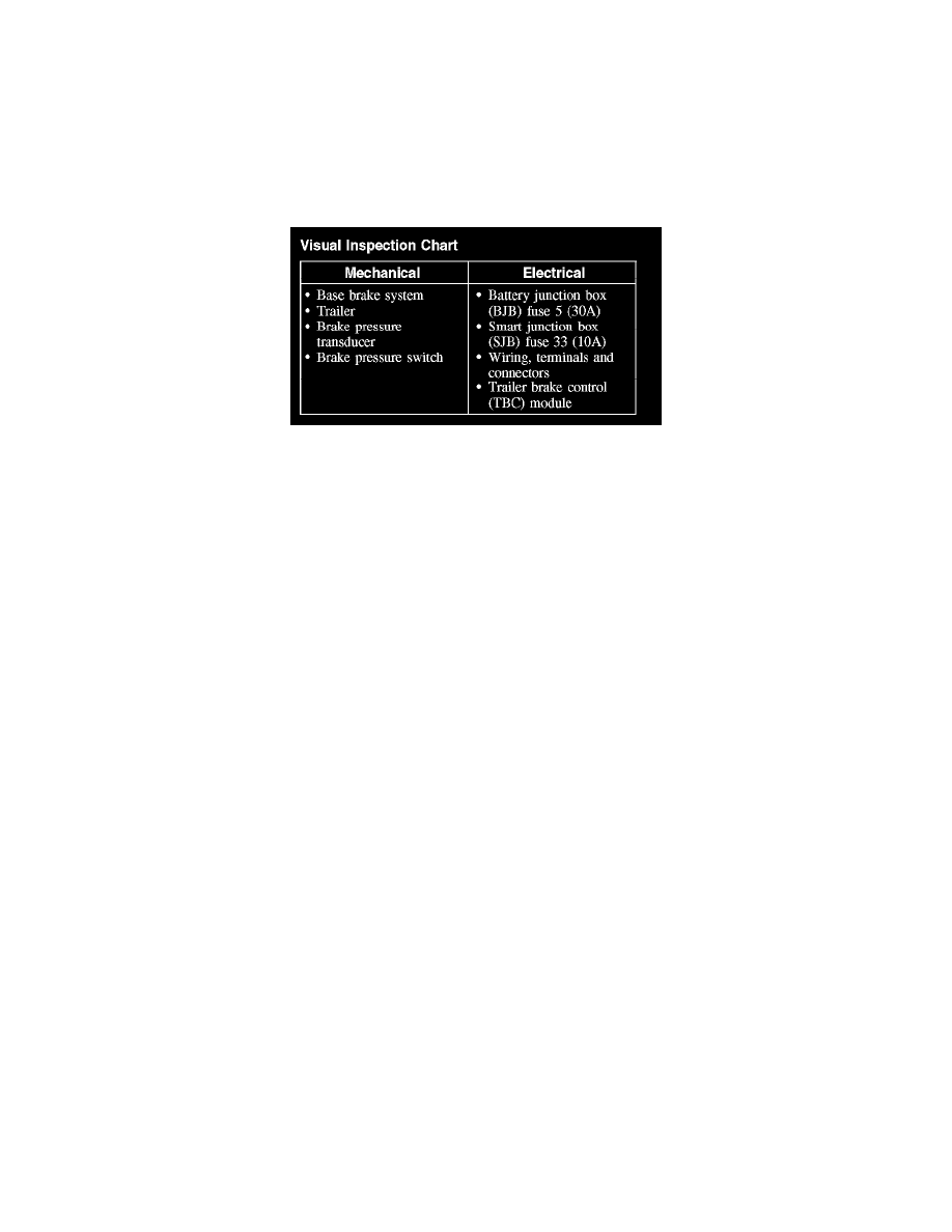
5. Visually inspect for obvious signs of mechanical or electrical damage.
Visual Inspection Chart
Visual Inspection Chart
6. If an obvious cause for an observed or reported concern is found, correct the cause (if possible) before proceeding to the next step.
7. NOTE: Make sure to use the latest scan tool software release.
If the cause is not visually evident, connect the scan tool to the data link connector (DLC).
8. NOTE: The vehicle communication module (VCM) LED prove out confirms power and ground from the DLC are provided to the VCM.
If the scan tool does not communicate with the VCM:
^
check the VCM connection to the vehicle.
^
check the scan tool connection to the VCM.
^
refer to Information Bus (Module Communications Network) to diagnose no communication with the scan tool.
9. If the scan tool does not communicate with the vehicle:
^
verify the ignition key is in the ON position.
^
verify the scan tool operation with a known good vehicle.
^
refer to Information Bus (Module Configuration) to diagnose no response from the PCM.
10. Carry out the network test.
^
If the scan tool responds with no communication for one or more modules, refer to Information Bus (Multiplex Communications Network).
^
If the network test passes, retrieve and record continuous memory DTCs.
11. Clear the continuous DTCs and carry out the self-test diagnostics for the TBC module.
12. If the DTCs retrieved are related to the concern, go to the Trailer Brake Control (TBC) Module DTC Chart. For all other DTCs, refer to Body
Control Systems (Multifunction Electronic Control Module). See: Diagnostic Trouble Code Descriptions
13. If no DTCs related to the concern are retrieved, GO to Symptom Chart. See: Symptom Related Diagnostic Procedures
Inspection and Verification
Inspection and Verification
NOTE: A trailer brake emulator tool is available to verify that the TBC module and vehicle wiring are functioning correctly.
1. Verify the TBC system is correctly installed by checking that the vehicle is equipped with a brake pressure transducer on the master cylinder. If the
brake pressure transducer is not present, then the TBC system has been installed incorrectly.
2. Verify the customer concern.
3. NOTE: The TBC system does not function with electric-over-hydraulic or surge trailer brake types.
Verify that the trailer brakes are electric-actuated drum type brakes.
4. Verify the vehicle stoplamps operate correctly by applying and releasing the brake pedal with the ignition switch in the OFF position and the
trailer disconnected. If the stoplamps do not operate correctly, refer to Lighting and Horns. If the vehicle stoplamps operate correctly, proceed to
the next step.
5. Visually inspect for obvious signs of mechanical or electrical damage.