
F 350 4WD Super Duty V8-6.4L DSL Turbo (2008)
Install the manual control lever shaft retaining pin into the case.
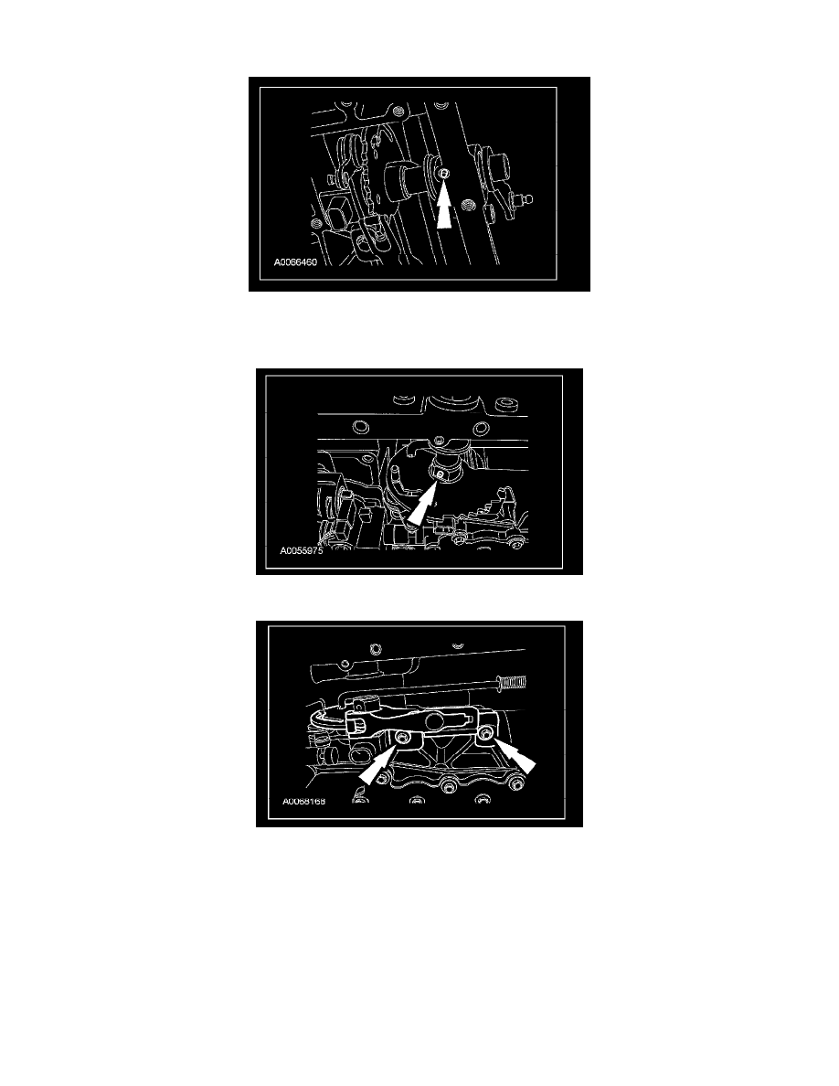
4. NOTE: When the retaining pin is installed correctly, 2 mm (0.08 inch) of the pin will be exposed.
Install a new manual control valve detent lever shaft retaining pin.
5. Tighten the bolts to 10 Nm (89 inch lbs.).
6. Connect the TR sensor electrical connector.