
F 350 4WD Super Duty V8-6.4L DSL Turbo (2008)
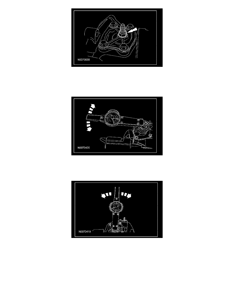
29. Rotate the input shaft to the left stop and then back-off approximately 45 degrees.
30. Using a dial or digital torque wrench and a crows foot wrench, slowly and evenly rotate the input shaft clockwise 1/2 turn (180 degrees), starting
from the 45 degree position. This torque reading is the preload torque.
^
Record the preload torque.
^
The preload torque must be within 0.34-1.36 Nm (3-12 inch lbs.).
31. Rotate the input shaft to its center of travel (approximately 1.5 turns from either stop). Place the torque wrench on the input shaft with the handle
in the vertical position. Rotate the torque wrench slowly and evenly 1/4 turn (90 degrees) from each side of center. This torque reading is the
on-center torque.
^
Record the torque measured on or near center.
32. NOTE: The on-center torque must be 1.01-1.47 Nm (9-13 inch lbs.) greater than preload torque without exceeding a total of 2.32 Nm (20.5 inch
lbs.). The on-center torque minus the preload torque is the meshload torque.
If necessary, carry out the following steps to adjust the on-center torque.
33. NOTE: Rotate the meshload adjusting screw clockwise to increase the on-center torque and counterclockwise to decrease the on-center torque.
Rotate the meshload adjusting screw until the on-center and meshload torque readings fall within the specified values.
34. While holding the meshload adjusting screw, tighten the meshload adjusting screw locknut to 31 Nm (23 ft. lbs.).