
F 350 4WD Super Duty V8-6.4L DSL Turbo (2008)
3. Inspect the driveshaft for damage, undercoating or incorrectly seated U-joints. Rotate the driveshaft slowly by hand and feel for binding or end
play in the U-joint trunnions. Remove the driveshaft. For additional information, refer to Drive/Propeller Shafts, Bearings and Joints. Inspect the
slip yoke splines for any galling, dirt, rust or incorrect lubrication. Clean the driveshaft or install new U-joints as necessary. Install a new
driveshaft if damaged. After any corrections or new components are installed, recheck for the vibration at the road test speed.
-
If the vibration is gone, test drive the vehicle.
-
If the vibration persists or the driveshaft passes visual inspection, measure the driveshaft runout.
Driveshaft Runout
1. Install the Dial Indicator Gauge with Holding Fixture. Rotate the driveshaft by turning the axle and measure the runout at the front, the center and
the rear of the driveshaft.
-
If the runout exceeds 1 mm (0.040 in) at the front or center, install a new driveshaft.
-
If the front and center is within 1 mm (0.040 in), but the rear runout is not, index-mark the rear runout high point and proceed to Step 2.
-
If the runout is within 1 mm (0.040 in) at all points, recheck for vibration at road test speed. If the vibration persists, balance the driveshaft.
For additional information, refer to Driveshaft Balancing in this procedure.
2. NOTE: Circular pinion flanges can be turned in 90 degree or one-fourth increments. Half-round pinion flanges are limited to 2 positions.
Index-mark the driveshaft to the pinion flange. Disconnect the driveshaft and rotate it 180 degrees. Reconnect the driveshaft. Recheck the runout at
the rear of the driveshaft.
-
If the runout is still over specification, mark the high point and proceed to Step 3.
-
If the runout is within specification, check for the vibration at the road test speed. If the vibration is still present, balance the driveshaft. For
additional information, refer to Driveshaft Balancing in this procedure.
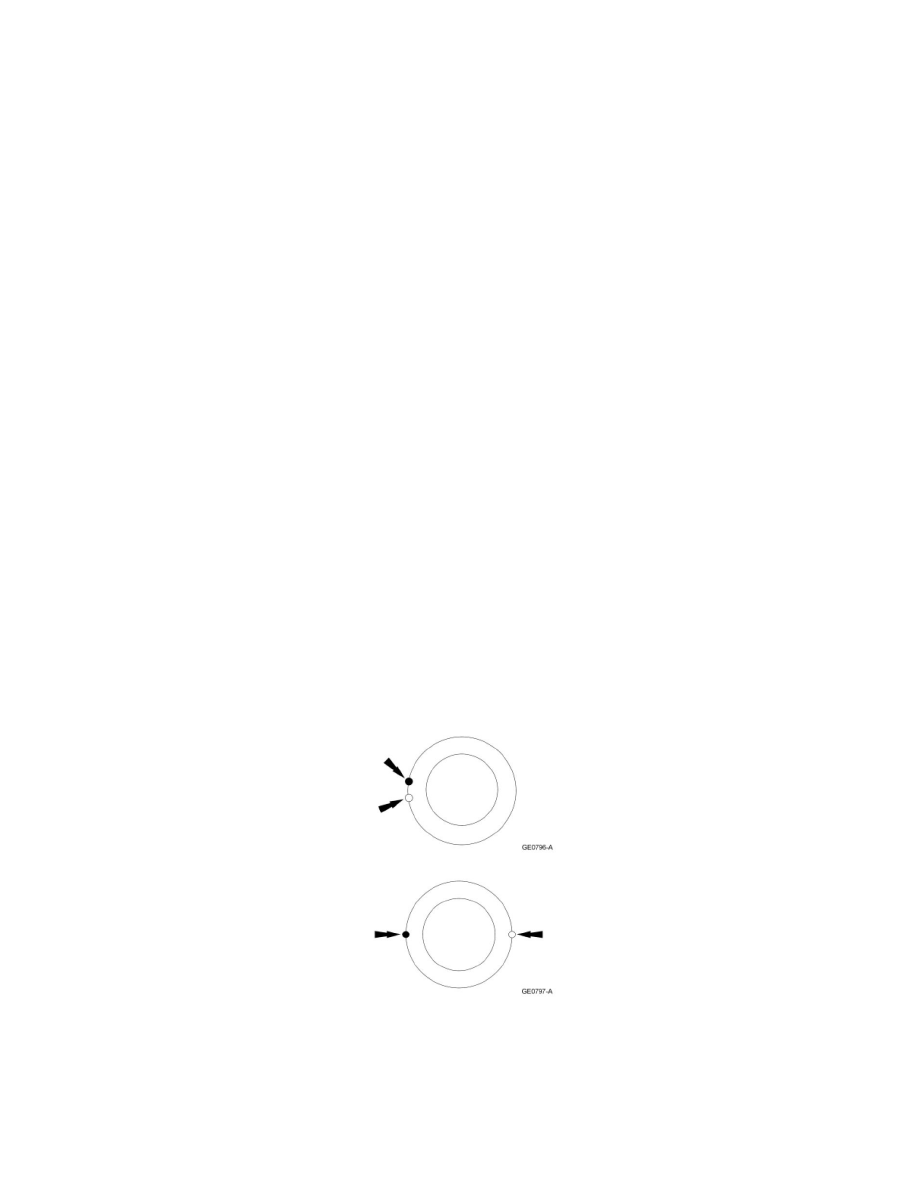
3. Excessive driveshaft runout can originate in the driveshaft itself or from the pinion flange. To find the source, compare the 2 high points
previously determined.
-
If the index marks are close together, within 25 mm (1 in), the driveshaft is eccentric. Install a new driveshaft.
-
If the marks are on opposite sides of the driveshaft, 180 degrees apart, the slip yoke or pinion flange is responsible. Check the pinion flange
runout. If the pinion flange runout exceeds specifications, a bent pinion is indicated.
-
If the pinion flange and pinion runouts are within specifications, road test and check for the vibration at the road test speed. If the vibration
persists, balance the driveshaft. For additional information, refer to Driveshaft Balancing in this procedure.
Driveshaft Balancing - Using the Mastertech(R) Series MTS 4000 Driveline Balance and NVH Analyzer (Vetronix)
All vehicles
1. Install the Mastertech(R) Series MTS 4000 Driveline Balance and NVH Analyzer (Vetronix) to the vehicle.
2. Working under the vehicle, install an accelerometer. The accelerometer can be attached and mounted near either the transmission or differential