F 450 2WD Super Duty V10-6.8L VIN V (2005)

3. Install the intake manifold bolts and tighten in 2 stages in the sequence shown.
^
Stage 1: Tighten to 2 Nm (18 inch lbs.).
^
Stage 2: Tighten to 10 Nm (89 inch lbs.).
4. Connect the throttle position (TP) sensor and electronic throttle control electrical connectors.
5. Connect the engine wiring harness position retainers to the intake manifold.
6. Connect the brake booster vacuum hose to the intake manifold.
7. Connect the positive crankcase ventilation (PCV) tube quick connect coupling to the intake manifold.
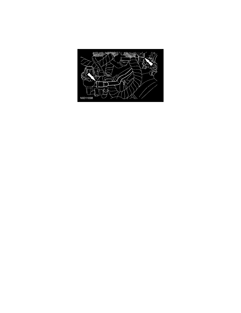
8. Position the evaporative emissions (EVAP) Tube and connect the quick connect couplings.
9. Connect the 2 heated PCV coolant hoses to the intake manifold.
10. Connect the 10 fuel injector electrical connectors.
11. Connect the fuel rail pressure and temperature sensor electrical connector and vacuum connector.
12. Connect the intake manifold runner control (IMRC) actuator electrical connector.
13. Connect the fuel supply spring lock coupling to the fuel rail.
14. Connect the heater coolant hose to the coolant crossover assembly.
15. Connect the heated PCV coolant hose to the coolant crossover assembly.
16. Connect the upper radiator hose to the thermostat housing.
17. Install the generator.
18. Install the air cleaner outlet pipe.
19. Fill and bleed the engine cooling system.
